
Manual


1
1-4
1 Before Use
Part Names and Functions
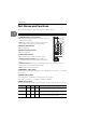
This section describes the name and functions of each component.
CC-Link communication unit LK-CC100
L RUN (Operating status) indicator
• Lit: Data communication between the master and local
stations (when lit green).
• Unlit: Data communications timed out (indicator will
light up again when data is received normally).
SD (Send data) indicator
• Lit: Sending data.
RD (Receive data) indicator
• Lit: Receiving data.
L ERR (error) indicator
• Lit: A communications error exists (when lit red).
• Flashing at regular intervals: Station number or
communication speed change detected while power
was on.
• Flashing irregularly: Terminator (terminating resistor) is set incorrectly, or noise is
affecting the unit or CC-Link dedicated cable.
• Unlit: Communications are normal.
STATION No. setting switch
Sets the station number (setting range: 1 to 64). x10 indicates the tens place, x1 indicates
the ones place.
B RATE setting switch
Sets the baud rate. The baud rate settings can be set as follows.
0: 156 kbps, 1: 625 kbps, 2: 2.5 Mbps, 3: 5 Mbps, 4: 10 Mbps
MODE setting switch
Sets the communication mode. The communication mode settings can be set as follows.
Switch setting Multiple Station Vers ion Remark
0 1 1 - Not supported (Disables control input, tolerance comparison
and readout of measurement values for any OUT).
1 1 2 1.1 Disables control input, tolerance comparison and readout of
measurement values for OUT03 and higher.
2 1 3 1.1 Disables control input, tolerance comparison and readout of
measurement values for OUT05 and higher.
L RUN
SD
RD
L ERR
10
LK-CC100
0
9
8
7
6
5
4
3
2
1
1
0
9
8
7
6
5
4
3
2
1
B RATE
SLD
DG
DB
D
A
0
9
8
7
6
5
4
3
2
1
MODE
0
F
E
D
C
B
A
9
8
7
6
5
4
3
2
1
STATION No.
(
FG
)
햲
햳
햴
햵
햶
햷
햸
햹
햺