96M11549 CC-Link Communication Unit for the LK-G5000 Series LK-CC100 DeviceNet Communication Unit LK-DN100 User's Manual Read this manual before use. Keep this manual in a safe place for future reference.
Introduction This manual describes the basic operations and hardware functions of the LK-CC100 and LK-DN100. Before using the LK-CC100 and LK-DN100, read this manual carefully to ensure complete understanding so that you can take full advantage of these product's performance and functions. Keep this manual in a safe place for future reference. Please deliver this manual to the end users of this product.
Safety Precautions General cautions • At startup and during operation, be sure to monitor the functions and performance of the LK-CC100 and LK-DN100. • It is recommended that you take substantial safety measures to avoid any damage in case of product failure. • Do not modify the LK-CC100 or LK-DN100 or use it in any way other than as described in the specifications. The warranty will be voided in such cases.
CAUTION Ensuring safe operation Do not block the vent holes on the unit. The rise in the internal temperature may cause product failure. Installation environment To use the LK-CC100 or LK-DN100 properly and safely, avoid installing it in the following locations. Doing so may lead to product breakdown.
Contents Introduction............................................... 2 Safety Precautions ................................... 3 General cautions ................................ 3 WARNING .......................................... 3 CAUTION ........................................... 4 Other considerations .......................... 4 Precautions on CE Marking................ 4 Contents ................................................... 5 Chapter 1 Before Use System Configuration .........................
Before Use 1 1 System Configuration..........................................................1-2 Checking the Package Contents ........................................1-3 Part Names and Functions .................................................1-4 Mounting/Connecting the Units .........................................
1 Before Use System Configuration The LK-CC100 and LK-DN100 can be used along with commercially-available devices for various purposes. 1 Enables control and measured value reading through RS-232C communication or the parallel I/O board of the PC. LK-G5000 Series Indicator, buzzer Issues an alarm depending on the comparator result output.
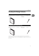
1 Before Use Checking the Package Contents LK-CC100 (CC-Link communication unit) CC-Link communication unit LK-CC100: 1 User's Manual: 1 Resistors • 110 1/2W: 2 • 130 1/2W: 2 1 Screwdriver: 1 00 C1 -C LK L RU N SD RD R STATION No. L ER 10 1 TE B RA DE MO ) (FG D SL DG DB DA LK-DN100 (DeviceNet communication unit) DeviceNet communication unit LK-DN100: 1 User's Manual: 1 Metal-film resistor 121 1% 1/4W: 2 Screwdriver: 1 00 N1 -D LK MS 10 1 STATION No.
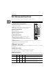
1 Before Use Part Names and Functions This section describes the name and functions of each component. CC-Link communication unit LK-CC100 L RUN (Operating status) indicator 햲 햳 햴 햵 LK-CC100 L RUN SD RD SD (Send data) indicator 901 10 901 45 6 23 1 STATION No. L ERR 23 45 6 • Lit: Data communication between the master and local stations (when lit green). • Unlit: Data communications timed out (indicator will light up again when data is received normally). 78 78 901 • Lit: Sending data.
1 Before Use Switch setting Multiple Station Version Remark 3 1 4 1.1 Disables control input, tolerance comparison and readout of measurement values for OUT07 and higher. 4 2 1 2.0 Disables control input or tolerance comparison for any OUT, and disables readout of measurement values for OUT3 and higher. 5 2 2 2.0 Disables control input or tolerance comparison for OUT05 and on, and disables readout of measurement values for OUT07 and higher. 6 2 3 2.
1 Before Use DeviceNet communication unit LK-DN100 MS (Status) indicator 햲 LK-DN100 MS 햳 901 45 6 23 10 901 45 6 23 1 78 EF012 6789A 345 Node Address NS 78 BCD 1 Displays the status of the LK-DN100. • Lit green: Normal operation. • Lit red: An unrecoverable alarm exists (caused when wrong switches are selected at start up). • Flashing red: A recoverable alarm exists (can be caused by turning the rotary switch after start up).
1 Before Use Mounting/Connecting the Units Connecting the communication unit 1 Connect the LK-CC100 CC-Link communication unit or the LK-DN100 DeviceNet communication unit to the controller. CAUTION Turn off the power of the LK-G5000 Series before connecting the communication unit. Otherwise, you may suffer a shock or damage the unit. 1 Connect the communication unit by aligning its connector to the connector on the left side of the LK-G5000.
1 Before Use 1 1-8
Connecting to CC-Link 2 2 Typical CC-Link System Configuration............................. 2-2 Connecting to the Field Network....................................... 2-4 Changing the CC-Link Communication Unit Settings..... 2-7 Creating the Ladder Program ...........................................2-19 Timing Diagrams ..............................................................
2 Connecting to CC-Link Typical CC-Link System Configuration Typical system configuration using CC-Link Host device: PLC, etc. (CC-Link master unit) PC for setup 2 LK-H02*/H05* series head LK-G5001 + LK-CC100 RS-232C/USB/Ethernet -G5 00 Terminator connection for KV-CL20, etc. 0 LK (V) (A) 0V ON ER LAS 1 (V) (A) 100 -CC LK L RUN SD RD 10 1 STATION No.
2 Connecting to CC-Link Special notes for using a CC-Link system Take note of the following when using the LK-CC100 in a CC-Link network. • The LK-CC100 is a network controller for CC-Link Ver. 2.00 or Ver. 1.10. If using the LKCC100 on a CC-Link Ver. 2.00 network, it must be connected to a master device compatible with CC-Link Ver. 2.00. The LK-CC100 operates as a Ver. 1.10 unit when the extended cyclic setting is set to single. It operates as a Ver. 2.00 unit at double or faster.
2 Connecting to CC-Link Connecting to the Field Network To connect to the master device or network controller on the field network using a multidrop connection, or to connect other slave devices, connect a communication cable that supports each field network to the field network connector. 2 Preparing the communication cable Use a communication cable dedicated for CC-Link (Ver. 1.10 or higher). 1 Remove the sheath (outer insulation) from the cable. Approx.
2 Connecting to CC-Link Connecting the wiring cable Connect the prepared wiring cable to the field network connector (terminal block). Reference The field network connector is designed for multidrop connection of slave devices. 1 2 Insert each signal line into the holes in the connector. Insert into corresponding connector NOTE Before inserting the communication cable, loosen the connector clamp screws. 2 Secure each signal line by tightening the clamp screws on the side of the connector.
2 Connecting to CC-Link Wiring to the CC-Link controller (LK-CC100) The LK-CC100 field network connector (terminal block) is to be wired as explained below. 2 Terminal name Function FG Functional ground terminal. Ground to a ground resistance of 100 ohms or less. SLD Shield. Connect shield wire from the dedicated CC-Link cable supporting Ver. 1.10 (OP-79426, OP-79427, etc.).
2 Connecting to CC-Link Changing the CC-Link Communication Unit Settings This section explains the principle and operation of the CC-Link communication unit (LKCC100). NOTE This manual describes only those functions and settings of the CC-Link master device necessary for communicating with the LK-CC100. Refer to the manual supplied with the master device for details on functions and settings between the CC-Link master device and a PLC.
2 Connecting to CC-Link Control using CC-Link This section explains how to use a PLC to control the LK-CC100 configured for a CC-Link network. NOTE 2 This section describes only those functions and settings of the CC-Link master station necessary for communicating with the LK-CC100. Refer to the manual supplied with the CC-Link master station and PLC for details on functions and settings of each device.
2 Connecting to CC-Link RY (Remote outputs) RY (remote outputs) are control signals sent from the CC-Link master station to the LK-CC100. LKCC100 Read control buffer Signal direction CC-Link master station RY (Remote outputs) Signal name Explanation RY (n+0) CHG_PRG_REQ • Requests to change to the program number stored in SET_PRG_NUM at the rising edge from OFF (0) ON (1). • Ends the request at the falling edge from ON (1) OFF (0).
2 Connecting to CC-Link LKCC100 Signal direction Read control buffer 2 CC-Link master station RY (Remote outputs) Signal name Explanation RY (n+16*m+3) OUTm_TIM_ON_REQ • Requests timing ON to OUTm at the rising edge from OFF (0) ON (1). • Ends the request at the falling edge from ON (1) OFF (0). RY (n+16*m+4) System reserved RY (n+16*m+5) OUTm_TIM_OFF_REQ • Requests timing OFF to OUTm at the rising edge from OFF (0) ON (1).
2 Connecting to CC-Link RWw (Remote registers) RWw (remote registers) refers to the area where parameters sent from the CC-Link master station to the LK-CC100 are stored. LKCC100 Read data buffer Signal direction CC-Link master station RY (Remote outputs) Signal name Explanation RWw (n+0) SET_PRG_NUM Sets the program selection number from 0 to 7. RWw (n+1) System reserved System reserved .. . n: varies according to the station number of the LK-CC100.
2 Connecting to CC-Link LKCC100 Signal direction Write control buffer CC-Link master station RY (Remote outputs) Signal name Explanation RX (n+13) CHG_PRG_ENBLE Turns ON (1) when program changeover is possible. RX (n+14) READY_FLAG • Turns ON (1) when the controller is not in setting mode, communicating, running, Able Tuning, or setting scaling from measurement data. • When OFF (0), the ***-ERR corresponding to the ***-REQ turns ON (1).
2 Connecting to CC-Link LKCC100 Write control buffer Signal direction CC-Link master station RY (Remote outputs) Signal name RX (n+16*m+15) Explanation System reserved RX (n+16*13+0) System reserved System reserved .. . 2 • n: varies according to the station number of the LK-CC100. • m (1 to 12): corresponds to the OUT number. m = 1 for OUT01, m = 2 for OUT02, etc. • ***-ACQ and ***-ERR turn OFF (0) at the falling edge of ***-REQ from ON(1) OFF(0).
2 Connecting to CC-Link Setting and programming The following settings and program are required to control the LK-CC100 using CC-Link. Set communication conditions 2 Set data size Set the LK-CC100 communication speed and slave ID (station number). Calculate and set the data size required for communication. Refer to "Link" (Page 2-14) for details. On the CC-Link master station, set the link area for the LK-CC100. Create a program according to the settings.
2 Connecting to CC-Link Memory allocation example This example shows how to make the following settings. Memory allocation This example assumes the CC-Link master station has the following memory allocation settings.
2 Connecting to CC-Link Example for a KEYENCE PLC LK-CC100 Signal direction CC-Link master station Device Signal name Read control buffer R32000 CHG_PRG_REQ 2 R32001 R32002 SYNC_TIM_ON_REQ R32003 R32004 SYNC_TIM_OFF_REQ R32005 R32006 SYNC_ZERO_ON_REQ R32007 .. . R32408 Read data buffer Write control buffer .. .
2 Connecting to CC-Link LK-CC100 Signal direction CC-Link master station Device Signal name Write data buffer DM10500 CUR_PRG_NUM DM10501 SYSTEM_ERR_NO DM10502 COUNTER_LO DM10503 COUNTER_HI DM10504 OUT1_LO DM10505 OUT1_HI .. . 2 .. .
2 Connecting to CC-Link LK-CC100 Signal direction CC-Link master station Device Signal name Write control buffer X1000 CHG_PRG_ACQ X1001 CHG_PRG_ERR X1002 SYNC_TIM_ON_ACQ 2 X1003 SYNC_TIM_ON_ERR X1004 SYNC_TIM_OFF_ACQ X1005 SYNC_TIM_OFF_ERR X1006 SYNC_ZERO_ON_ACQ X1007 SYNC_ZERO_ON_ERR .. . Write data buffer .. .
2 Connecting to CC-Link Creating the Ladder Program Acquiring measurement data, tolerance comparator results, various statuses (auto-zero, timing, system error), and program number settings Create the ladder program as follows. 1 Check the status. 2 Store the counter value. 3 Check for counter value updates. 4 Acquire data. 2 Verify the SYSTEM_ERR_FLAG is OFF and READY_FLAG is ON. Store the current counter value (COUNTER_LO and COUNTER_HI).
2 Connecting to CC-Link Programming a control input Create the ladder program as follows. 1 Check the status. 2 Set the control parameter. 3 Send the control input request. 4 Check the control input status. 5 Check the control input result. 2 • Verify the SYSTEM_ERR_FLAG is OFF and READY_FLAG is ON. • To request a program change, verify CHG_PRG_ENBLE is ON. • Verify ***_ACQ is OFF. To request a program change, store the program number in SET_PRG_NUM.
2 Connecting to CC-Link Timing Diagrams This is the timing diagram for a control input. • OUT: Master slave • IN: Slave master • Internal: Internal processing at the slave NOTE • Control inputs that do not have the ***_STATE flag follow the same timing except that the ***_STATE flag is omitted. • The X axis shows the correct timing but not the exact time. Normal timing (status change from OFF ON) Verify ***_ACQ is OFF, then turn ***_REQ ON.
2 Connecting to CC-Link Internal processing time ***_REQ ON ***_ACQ ON t 2 The following table describes time t for each command.
Connecting to DeviceNet 3 3 Typical DeviceNet System Configuration ......................... 3-2 Connecting to the Field Network....................................... 3-4 Changing the DeviceNet Communication Unit Settings . 3-7 Creating the Ladder Program ...........................................3-18 Timing Diagrams ..............................................................
3 Connecting to DeviceNet Typical DeviceNet System Configuration Typical system configuration using DeviceNet Host device: PLC, etc. (DeviceNet master unit) PC for setup 3 LK-H02*/H05* series head LK-G5001 + LK-DN100 RS-232C/USB/Ethernet -G5 00 Terminator connection for KV-DN20, etc. 0 LK (V) (A) 0V ON ER 1 LAS (V) (A) 100 -DN LK MS 10 1 STATION No.
3 Connecting to DeviceNet Special notes for using a DeviceNet system Take note of the following when using the LK-DN100 in a DeviceNet network. • DeviceNet supports up to 64 connected devices. This includes the master, slaves, and configurable devices. • The maximum total length of the entire DeviceNet network is 500 m (at 125 kbps). Refer to the following table for the relation between communication speed and maximum cable length. Type of cable Thick cable Thin cable Communication Max.
3 Connecting to DeviceNet Connecting to the Field Network To connect to the master device or network controller on the field network using a multidrop connection, or to connect other slave devices, connect a communication cable that supports each field network to the field network connector. Preparing the communication cable 3 Use a 5-wire communication cable dedicated for DeviceNet. 1 Remove the sheath (outer insulation) from the cable. Sheath 6 mm max. Braided shield wires Approx.
3 Connecting to DeviceNet Connecting the wiring cable Connect the prepared wiring cable to the field network connector (terminal block). Reference The field network connector is designed for multidrop connection of slave devices. 1 Insert each signal line into the holes in the connector. Insert into corresponding connector 3 NOTE Before inserting the communication cable, loosen the connector clamp screws. 2 Secure each signal line by tightening the clamp screws on the side of the connector.
3 Connecting to DeviceNet Wiring to the DeviceNet controller (LK-DN100) The LK-DN100 field network connector (terminal block) is to be wired as explained below.
3 Connecting to DeviceNet Changing the DeviceNet Communication Unit Settings This section explains the principle and operation of the DeviceNet controller (LK-DN100). NOTE This manual describes only those functions and settings of the DeviceNet master device necessary for communicating with the LK-DN100. Refer to the manual supplied with the master device for details on functions and settings between the DeviceNet master device and a PLC.
3 Connecting to DeviceNet Master settings To connect the LK-DN100 to the DeviceNet master, it is necessary to configure the slave attribute and memory allocation settings. Slave attributes Set the slave settings for communication format, I/O size, etc., on the master. The master can also be set by reading an EDS file for the LK-DN100 using the master setting software. 3 Memory allocation settings This setting affects non-programmed data exchange between the slave and master.
3 Connecting to DeviceNet Control using DeviceNet This section explains how to use a PLC to control the LK-DN100 configured for the DeviceNet network. NOTE This section describes only those functions and settings of the DeviceNet master unit necessary for communicating with the LK-DN100. Refer to the manual supplied with the DeviceNet master unit and PLC for details on functions and settings of each device.
3 Connecting to DeviceNet Output control buffer The output control buffer refers to control signals sent from the DeviceNet master node to the LK-DN100. LKDN100 Signal direction Read control buffer 3 3-10 DeviceNet master node Offset Signal name Explanation Bit (0) CHG_PRG_REQ • Requests to change to the program number stored in SET_PRG_NUM at the rising edge from OFF (0) ON (1). • Ends the request at the falling edge from ON (1) OFF (0).
3 Connecting to DeviceNet LKDN100 Read control buffer Signal direction DeviceNet master node Offset Signal name Explanation Bit (16*m+3) OUTm_TIM_ON_REQ • Requests timing ON to OUTm at the rising edge from OFF (0) ON (1). • Ends the request at the falling edge from ON (1) OFF (0). Bit (16*m+4) System reserved Bit (16*m+5) OUTm_TIM_OFF_REQ • Requests timing OFF to OUTm at the rising edge from OFF (0) ON (1). • Ends the request at the falling edge from ON (1) OFF (0).
3 Connecting to DeviceNet Output data buffer The output data buffer refers to the area where parameters sent from the DeviceNet master node to the LK-DN100 are stored. 3 LKDN100 Signal direction Read data buffer DeviceNet master node Offset Signal name Explanation Word (14) SET_PRG_NUM Sets the program selection number from 0 to 7. Word (15) System reserved A word is 16 bits.
3 Connecting to DeviceNet LKDN100 Write control buffer Signal direction DeviceNet master node Offset Signal name Explanation Bit (14) READY_FLAG Turns ON (1) when the controller is not in setting mode, communicating, running, Able Tuning, or setting scaling from measurement data. Bit (15) SYSTEM_ERR_FLAG • Turns ON (1) when the controller or expansion unit has a system error. • When ON (1), all signals except SYSTEM_ERR_NO become invalid.
3 Connecting to DeviceNet Input data buffer The input data buffer refers to the area where the statuses of LK-DN100 are stored. LKDN100 Signal direction Write data buffer 3 DeviceNet master node Offset Signal name Explanation Word (14) CUR_PRG_NUM Stores the current program selection number from 0 to 7. Word (15) SYSTEM_ERR_NO Stores the system error number when the SYSTEM_ERR_FLAG turned ON (1). Word (16) COUNTER_LO Word (17) COUNTER_HI Stores the unsigned 32-bit counter value.
3 Connecting to DeviceNet Setting and programming The following settings and program are required to control the LK-DN100 using DeviceNet. Set communication conditions Set data size Set the LK-DN100 communication speed and slave ID (node address). Calculate and set the data size required for communication. Refer to "Data size settings:". On the DeviceNet master node, set the link area for the LK-DN100. Create a program according to the settings.
3 Connecting to DeviceNet Memory allocation example This example shows how to make the following settings. Memory allocation • Output area starting address: DM10700 • Input area starting address: DM10500 Memory allocation size 3 • Output data buffer size: 16 words regardless of setting • Input data buffer size: 42 words regardless of setting LK-DN100 Signal DeviceNet master node direction Offset Bit Signal name Read control buffer ← 0 CHG_PRG_REQ 1 − 2 SYNC_TIM_ON_REQ DM10700 − 3 .. .
3 Connecting to DeviceNet LK-DN100 Signal DeviceNet master node direction Offset Bit Write data buffer Signal name DM10514 DM10515 SYSTEM_ERR_NO DM10516 COUNTER_LO DM10517 COUNTER_HI DM10518 OUT1_LO DM10519 .. . OUT1_HI .. . .. .
3 Connecting to DeviceNet Creating the Ladder Program Acquiring measurement data, tolerance comparator results, various statuses (auto-zero, timing, system error), and program number settings Create the ladder program as follows. 1 3 2 Check the status. Verify the SYSTEM_ERR_FLAG is OFF and READY_FLAG is ON. Store the counter value. Store the current counter value (COUNTER_LO and COUNTER_HI). 3 Check for counter value updates. 4 Acquire data.
3 Connecting to DeviceNet Programming a control input Create the ladder program as follows. 1 Check the status. 2 Set the control parameter. 3 Send the control input request. 4 Check the control input status. 5 Check the control input result. • Verify the SYSTEM_ERR_FLAG is OFF and READY_FLAG is ON. • To request a program change, verify CHG_PRG_ENBLE is ON. • Verify ***_ACQ is OFF. 3 To request a program change, store the program number in SET_PRG_NUM.
3 Connecting to DeviceNet Timing Diagrams This is the timing diagram for a control input. • OUT: Master slave • IN: Slave master • Internal: Internal processing at the slave Reference 3 • Control inputs that do not have the ***_STATE flag follow the same timing except that the ***_STATE flag is omitted. • The X axis shows the correct timing but not the exact time. Normal timing (status change from OFF ON) Verify ***_ACQ is OFF, then turn ***_REQ ON.
3 Connecting to DeviceNet Internal processing time ***_REQ ON ***_ACQ ON t The following table describes time t for each command.
3 Connecting to DeviceNet 3 3-22
Specifications 4 4 Specifications ..................................................................... 4-2 Dimensions .........................................................................
4 Specifications Specifications CC-Link unit LK-CC100 Model LK-CC100 Name Network connection 4 CC-Link communication unit dedicated to LK-G5000 Series Supported CC-Link*1 version Ver. 1.10 (extended cyclic setting: single) Ver. 2.00 (extended cyclic setting: double or more)*2 Master unit CLPA-certified master unit (CC-Link Ver. 2.00/Ver. 1.10) No. of occupied stations 1 to 4 Communication speed 156 kbps, 625 kbps, 2.
4 Specifications LK-DN100 DeviceNet unit Model LK-DN100 Name DeviceNet communication unit dedicated to LK-G5000 Series Network connection Communication protocol DeviceNet*1 compliant Master unit ODVA-certified master unit Transmission speed 500 kbps, 250 kbps, 125 kbps Device type Generic Transmission medium Dedicated 5 cables (2 signal cables, 2 power supply cables, 1 shielding cable) Maximum trunk line cable length Thick cable: 500 m (at transmission speed 125 kbps) / 250 m (at 250 kbps) /
4 Specifications Dimensions LK-CC100 26.3 (13.2) 105.5 35.9 124 DIN rail 6 62.1 4 (3.2) 13.5 M4 Depth: 6 mm 14 128 (13.2) 13.5 (3.2) 6 124 26.
4 Specifications LK-DN100 26.3 (13.2) 105.5 35.9 124 DIN rail 6 62.1 4 (3.2) 13.5 M4 Depth: 6 mm 14 128 (13.2) 13.5 (3.2) 6 124 26.
4 Specifications 4 4-6
Appendices A Error Codes.........................................................................
Appendices Error Codes This section lists the error codes displayed by the LK-G5000 Series and the countermeasures. Display System error Error description Err-00 Head connection error Err-01 to 12 A Countermeasure Check the sensor head connection. Head 01 to head 12 error If there are errors with two or more sensor heads, the smallest error number among Err-01 to 12 is displayed. Err-13 Controller error Turn off the power once and turn it on again.
Appendices Display System error Error description Countermeasure Err-64 Parameter range error (OUT/Head No.) The number of sensor heads or OUT being used exceeds the active head/OUT count. Check the setting. Err-65 Parameter range error (Velocity/acceleration calculation method) The OUT set to the measurement type of "Velocity" or "Acceleration" was set to OUT for another measurement type or to AVE/P-P/MAX or other calculation between OUT. Check the setting.
Appendices
Appendices
Appendices Revision History Date of printing Version May 2009 1st edition December 2010 Revised 1st edition August 2012 Revised 2nd edition Revision
WARRANTIES AND DISCLAIMERS (1) KEYENCE warrants the Products to be free of defects in materials and workmanship for a period of one (1) year from the date of shipment. If any models or samples were shown to Buyer, such models or samples were used merely to illustrate the general type and quality of the Products and not to represent that the Products would necessarily conform to said models or samples.
Copyright (c) 2010 KEYENCE CORPORATION. All rights reserved.