
Manual


9
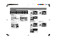
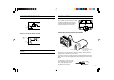
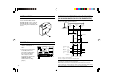
Input circuit (AUTO ZERO, synchronous, and laser emission stop)
Output circuit (Alarm, NEAR, and FAR)
Note: Use a non-voltage contact to connect or disconnect the input
terminals.
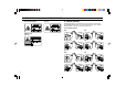
INPUT/OUTPUT CIRCUIT INSTALLATION
Controller
The controller can be mounted to a DIN
rail. When mounting or removing the
controller, pull the claw at the bottom
center in the direction of the arrow.
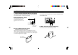
Connecting sensor head and controller
Connect the sensor head to the extension cable(s), and the extension
cable(s) to the controller as shown above.
To join the connectors, gently press them together and turn them to the
right or left to locate the engagement position, then press until a click is
heard.
To remove the connectors, hold
the connecting sleeve as shown
on the right, and pull it out in
the direction of the arrow.
IN
GND
3 kΩ
470 Ω
24 V
GND
NPN
Open-collector
output
6.8 Ω
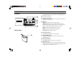
REMOTE
24 VDC IN GND
TIMING
ZERO
GND ALARM
GND
NEAR
FAR
+
-
LASER
OFF
ON
0
MON(V)
SPAN
SHIFT
ZERO/RESET
ZERO/RESET
TIMING
STABILITY
BRIGHT
DARK
LASER ON
1
2 3
MON(mA)
LK-031
Sensor head
Extension cable
(LK-C2 [2 m], LK-C5 [5 m],
LK-C10 [10 m])
Controller
H
IG
H
AUTO
G
AIN
LO
W