
Manual


7
Controller
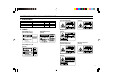
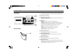
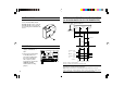
PART NAMES
11
11
1 DIP switches
Set alarm hold function, key-lock function, and averaging function.
22
22
2 Sensor head connector
33
33
3 Sensitivity setting switch
Changes the received light sensitivity according to the reflectance of
the target. (
➮
Refer to p. 15
)
44
44
4 Indicators
TIMING: Lights during synchronous (timing) input.
STABILITY: Lights yellow or green when a target is within the
measuring range. Lights red when a target is out of the measuring
range, or when the light quantity is insufficient or excessive.
BRIGHT: Lights when the light quantity is excessive.
DARK: Lights when the light quantity is insufficient.
LASER ON: Lights during laser emission.
55
55
5 SPAN adjustment keys
Finely adjusts the inclination of the analog output.
66
66
6 AUTO ZERO/RESET keys
Resets the analog output to 0 V (12 mA) at any point. Cancels
AUTO ZERO function.
77
77
7 SHIFT adjustment key
Finely adjusts the 0-point position of the analog output.
88
88
8 Operation indicator
Lights yellow or green when a target is within the measuring range.
Flashes yellow when a target is out of the measuring range, or when
the light quantity is insufficient or excessive.
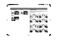
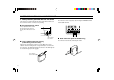
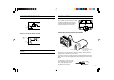
Sensor head
ONOFF
REMOTE24 VDC IN GND TIMING ZERO GND ALARM GND NEAR FAR
+-
SPANSHIFT
ZERO/RESET ZERO/RESET
TIMING STABILITY BRIGHT DARK LASER ON
123 HIGH AUTO
GAIN
LOW
0 MON(V) MON(mA)
LASER
2
1
3
4
5
6
7
LK-031
LASER ON
8