96M10799 Instruction Manual CCD Laser Displacement Sensor LK-2000 Series
CONTENTS SAFETY INFORMATION FOR LK-2000 SERIES Safety Information for LK-2000 series ............................................ 2 Safety Precautions on Laser Product ............................................. 3 Part Names ..................................................................................... 7 Connections .................................................................................... 8 Input/Output Circuit .........................................................................
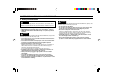
SAFETY PRECAUTIONS ON LASER PRODUCT IEC Class 2 [LK-031/036/081/086] 1. Classification Model LK-031/036 LK-081/086 FDA(CDRH) 21CFR Part 1040.10 Class II IEC/EN 60825-1 Class 2 DIN EN 60825-1 Class 2 LK-501 Class IIIb Class 3B Class 3B LK-503 Class II Class 2 Class 2 2. Labels FDA(CDRH) Class II [LK-031/036/081/086] CAUTION LASER RADIATIONDO NOT STARE INTO BEAM SEMICONDUCTOR LASER 655nm MAXIMUM OUTPUT 0.
SAFETY PRECAUTIONS ON LASER PRODUCT DIN Class 2 [LK-031/036/081/086] DIN Class 2 [LK-503] 3. Labels location FDA Warning labels are attached to the sensor head as shown below. The IEC/DIN Warning labels are packaged with the LK series. Affix the Warning labels on the sensor head as shown below. LK-031/036/081/086/503 IEC FDA DIN Class 3B [LK-501] LK-031 AVOID EXPOSURE LASER RADIATION IS EMITTED FROM THIS APERTURE.
SAFETY PRECAUTIONS ON LASER PRODUCT 4. Safety consideration CAUTION Use of controls or adjustments or the performance of procedures other than those specified herein may result in hazardous radiation exposure. 1) Class 3B/IIIb laser products • MPE (Maximum Permissible Exposure): 2.55 mW/cm2 (LK-501) • NOHD (Nominal Ocular Hazard Distance): 8 m (LK-501) from the aperture. WARNING Follow the instructions mentioned in this manual. Otherwise, injury to the human body (eyes and skin) may result.
SAFETY PRECAUTIONS ON LASER PRODUCT 5. Safety features provided with the LK series ■ Remote interlock terminal The LK series is provided with the following safety features. Make sure these features function correctly before operating. Laser emission can be stopped by disconnecting the REMOTE terminal from the GND terminal. ■ Key-operated laser switch A key-operated switch controls the LK series laser. Remove the key when the laser is not in use.
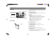
PART NAMES 1 DIP switches Set alarm hold function, key-lock function, and averaging function. Controller 1 2 0 MON(V) MON(mA) GAIN 3 1 2 3 TIMING DARK LASER ON 4 SPAN ZERO/RESET ZERO/RESET LASER OFF 24 VDC IN 3 Sensitivity setting switch Changes the received light sensitivity according to the reflectance of the target. (➮ Refer to p.
CONNECTIONS 9 Alarm output (N.C.) The output contact opens when measurement is impossible due to an insufficient or excessive light quantity, or due to the target being out of the measuring range. The output is normally closed. Analog Analog voltage current output (V) output (mA) 0V 13 14 15 A NEAR alarm output (N.C.) The output contact opens when a target is positioned closer than the measuring range. The output is normally closed. 1 2 3 4 F.G.
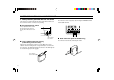
INPUT/OUTPUT CIRCUIT INSTALLATION Input circuit (AUTO ZERO, synchronous, and laser emission stop) Controller 24 V 3 kΩ IN The controller can be mounted to a DIN rail. When mounting or removing the controller, pull the claw at the bottom center in the direction of the arrow. 470 Ω GND Output circuit (Alarm, NEAR, and FAR) NPN Open-collector output Connecting sensor head and controller 0 MO N(V ) MO N(m A) 1 TIM SH IFT 2 ING 3 ST GA AB IN ILI TY BR 6.
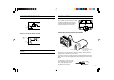
INSTALLATION OUTPUT CHARACTERISTICS AND LED INDICATOR [LK-031/036/081/086/501/503 IN LONG RANGE MODE] Sensor head Adjust the distance between the sensor head and target by checking the sensor head’s LED operation indicator. LK-031 Secure the LK-031/036 and LK081/086 with M4 screws, or the LK501/503 with M5 screws using the two mounting holes indicated by the arrows.
OUTPUT CHARACTERISTICS AND LED INDICATOR [LK-501/503 IN HIGH-PRECISION MODE] SPOT DIAMETER 5 mm (15 mm)* 30 mm (80 mm)* LK-501 Adjust the distance between the sensor head and target by checking the sensor head’s LED operation indicator.
SETTING Measuring distance LK-031/036/081/086/501/503 To measure the thickness of a moving object, place the target close to the reference position where the spot diameter is smallest. This assures the most stable detection. Border of different color or luster Correct Displacement in a hole Incorrect LK-031 LK-031 Approx. 30 mm (LK-031/036) Approx. 80 mm (LK-081/086) Approx. 350 mm (LK-501/503 in high-precision mode) Approx.
AUTO ZERO FUNCTIONS AUTO ZERO function Resets the output voltage to 0 V at the desired point within the measuring range. Changing the zero position enables the output range to be set at either -10 to 0 V, or 0 to 10 V. Example (LK-031/036) LK-031 When LOCK is set: The AUTO ZERO input is available only from the external input terminal. When the power is turned off, the value of the AUTO ZERO input is not stored, and the zero point is reset to the reference position.
FUNCTIONS SHIFT/SPAN Shift adjustment function Span adjustment function ZERO RESET Adjusts the analog value zero point using the UP/DOWN keys for shift adjustment. LK-031 RESET Adjusts the analog value inclination using the UP/DOWN keys for span adjustment. Use the span adjustment when the sensor head is tilted or the target surface condition affects the analog output characteristics. LK-031 LK-031 30.015 mm LK-031 30.015 mm V 2.
FUNCTIONS SENSITIVITY SETTING Sets an appropriate sensitivity according to the change in target surface condition. GAIN HIGH AUTO Example: Measurement of pin warpage In the measurement of the warpage of moving pins, the reflectance of the pin and gap change greatly during a short cycle. To measure such a target, set the sensitivity setting switch to LOW and measure only pins which have high reflectance. LOW 1 -03 LK Set the sensitivity to AUTO for normal use.
DIP SWITCHES FUNCTIONS Alarm hold function Key-lock function DIP switch 1 When DIP switch 1 is set to the upper position, the sensor does not produce the 12 V (31.2 mA) analog output during alarm output (range over/light quantity alarm), but retains the analog output value just prior to alarm output. This function is canceled when measurement is again possible.
FUNCTIONS DIP SWITCHES Response speed selection function Example: When LOW is set DIP switch 3 Set DIP switch 3 to select whether to output every measured value or the average of 8 measured values (moving average). LK -03 LOW HIGH 1 2 3 1 Analog output DIP switch (HIGH) Analog output DIP switch (LOW) LOW: Outputs the value of the average of 8 measured values. Offers more stable detection when the luster of the target varies greatly. HIGH: Outputs every measured value.
FUNCTIONS MEASUREMENT MODE SELECTION [WITH LK-501/503 ONLY] The LK-501/503 offers two measurement modes to be used according to the measurement conditions. Long-range mode Measures within a range of 250 to 750 mm. Use long-range mode to mount the sensor head at a distance from the target, or to obtain a long measurement range. High-precision mode Measures within a range of 250 to 450 mm. Use high-precision mode to obtain high repeatability.
HINTS ON CORRECT USE ■ Noise interference (The sensor head is case-grounded.) CAUTION Isolate the sensor cable and extension cable(s) from high-tension lines or power lines, otherwise the sensor may malfunction or the laser diode may deteriorate due to noise interference. • If noise is present at the surface where the sensor head is mounted, install insulator between the mounting surface and the sensor head. • Earth-ground the frame grounding terminal.
INPUT CHARACTERISTICS Timing diagram Minimum input time Data in ( )* applies to the LK-081. Data in ( )** applies to the LK-501/503. Analog output 12 V Synchronous (timing) input 10ms 2ms (20 ms)* (2.5 ms)* Sensitivity: AUTO: 100 ms (4.5 ms)** Sensitivity: HI or LO: 16 ms 0V Laser emission stop input ON Synchronous (timing) input ON AUTO ZERO input ON OFF ON OFF OFF OFF Note: The analog output is retained for the following amount of time after disconnection of the synchronous input terminal.
SPECIFICATIONS Sensor head Controller Measurement mode Reference distance Measuring range Light source Maximum output Pulse duration Wavelength FDA(CDRH) 21CFR Part 1040.
CHARACTERISTICS Angle characteristics Changes the span of the analog output when a white ceramic target is tilted by ±30° (Typical) LK-031/036 LK-501/503 +25 mV Analog A voltage (V) LK-031 Analog voltage (V) 5 A 5 A -30° (-15°) +30° (+15°) -10 mV 0 30 35 Distance (mm) 25 35 Distance (mm) -5 Data in ( ) applies to the LK-036. Data in ( ) applies to the LK-036.
MUTUAL INTERFERENCE DIMENSIONS Interference range Sensor head Interference will occur only when the beam spot of another sensor is positioned inside of the shadowed area. LK-031/036 LK-031/036 Unit: mm ø15 43 LK-081/086 ø7 500 LK-081 LK-031 85 2 x ø4.5 (mounting hole) 26 25 15 mm 76 67 26 mm 95 mm 65 mm 46 mm 34 mm 40° 4 30 mm 12 mm 25 to 35 13.5 10 mm 8 mm LK-501/503 ±1 mm 35 mm 13 mm ø15 LK-081/086 ;; 13 ±3 mm 43 LK-501 ø7 500 226 mm 750 mm 95 2 x ø4.
DIMENSIONS Unit: mm Controller LK-501/503 LK-2001/2011/2101/2111/2501/2503 33.5 120 2 x ø5.4 (mounting hole) 47.8 43 90 79 Extension cable ø7, Cable length: 500 mm ø15 Cable length (m) 2 5 10 172 Model LK-C2 LK-C5 LK-C10 0 to 140° 5 250 to 750 (250 to 450) 140 8° (11°) 110 4 x ø5 (mounting hole) Measurement reference position 90 100 112 13.8 24 24.5 13 76 35.
WARRANTIES AND DISCLAIMERS (1) KEYENCE warrants the Products to be free of defects in materials and workmanship for a period of one (1) year from the date of shipment. If any models or samples were shown to Buyer, such models or samples were used merely to illustrate the general type and quality of the Products and not to represent that the Products would necessarily conform to said models or samples.
Copyright (c) 2010 KEYENCE CORPORATION. All rights reserved.