96M00261 User's Manual Operator Interface Panel KV-D20 kv_d20_manual.p65 1 08.3.
Safety Precautions This instruction manual describes the operation and function of the Operator Interface Panel. Read this manual carefully to ensure safe use and maximum performance from your KV-D20. Symbols The following symbols alert you to important messages. Be sure to read these messages carefully. Failure to follow instructions may lead to injury. (electric WARNING shock, burn, etc.) CAUTION Note: Failure to follow instructions may lead to product damage.
Note to User When using the NEW KV Series in the following conditions or environments, be sure to use the NEW KV Series with sufficient margin regarding the rating and functions, take appropriate safety precautions such as fail-safe, and contact our sales personnel if any questions arise.
Warranty Our products are thoroughly inspected before shipment. However, in the event of a malfunction, contact your nearest KEYENCE office. KEYENCE will replace or repair any defective parts free of charge for one year from the date of shipment from the factory. However, we shall not be responsible for any failure resulting from improper use, negligence, natural disaster or fire.
kv_d20_manual.p65 5 08.3.
Contents 1 Before Operation 8 1.1 Checking Package Contents ................................................................. 8 1.2 Part Names and Functions .................................................................... 9 1.3 Details about the KV-D20 .................................................................... 10 General specifications ....................................................................... 10 Functional specifications ....................................................
3 Examples of Ladder Programs 3.1 3.2 4 43 Basic Ladder Programs ....................................................................... 43 Before creating ladder programs ....................................................... 43 Basic ladder programs ....................................................................... 44 Examples of Ladder Programs ........................................................... 51 Example of displaying user messages ..............................................
1. Before Operation 1. Before Operation This section includes the names, functions, and details of the KV-D20 and information required before starting operation. 1 1.1 Checking Package Contents The KV-D20 package includes the following components. Before using the KVD20, check that all components have been included in the package. 7 6 5 4 3 2 1 0 KV-D20 Display Modular cable (2.5 m) OP-26487 Mounting fixture (2 pcs.) 8 kv_d20_manual.p65 8 08.3.
1. Before Operation 1.2 Part Names and Functions This section describes the part names and functions of the KV-D20. 1. Customized lamps 1 2. LCD display 2 3 1 4 5. Communication port (rear side) 6. Bit guide 7 6 5 4 3 2 1 0 F1 F2 F3 F4 3. Customized switches 4. Setting operation switch No. Name Function 1 Customized lamps Assigned to special utility relays. The LED illuminates when the corresponding relay turns on.
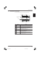
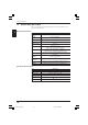
1. Before Operation 1.3 Details about the KV-D20 This section describes the general specifications, functional specifications, and dimensions of the KV-D20. 1 General specifications Item Specification Power supply voltage Supplied f r om t he communicat ion por t of t he K V (5 V DC) Current consumption 5 V DC, 180 mA max. (60 mA max.
1. Before Operation Dimensions ■ KV-D20 Panel thickness: 1.2 to 3.0 mm 1 75 112 67 34 5 133 (Including mounting fixtures) ■ Panel cutout 145 68 +1 0 105 +1 0 83 11 kv_d20_manual.p65 11 08.3.
1. Before Operation 1.4 Installation and Environment This section describes the panel mounting method and precautions for installation. Use environment This section describes environment, location, and wiring precautions for the KVD20. 1 ■ Locations Avoid installing the KV-D20 in the following locations: CAUTION • Locations in which the KV-D20 may be subjected to direct sunlight. • Locations in which the surrounding air temperature drops below 0°C or exceeds 50°C.
2. Overview and Operation Panel mounting ■ Precautions • Install the KV-D20 by holding the panel at the front and rear sides with the unit and mounting fixtures. Available panel thickness: 1.2 mm to 3.0 mm * • • • 1.2 to 3.0 mm If your panel has a thickness of 3.0 mm or more, contact your nearest KEYENCE office listed at the back of this manual. 2 To ensure maintainability, operability, and ventilation, keep as much distance as possible between the KV-D20 and the surrounding structure or components.
2. Overview and Operation 1.5 Inspection and Maintenance This section describes how to inspect and maintain the KV-D20. Inspection The KV-D20 may cause malfunctions due to loose modular cable connectors or mounting fixtures during long-term use. Be sure to regularly check the KV-D20 unit and connections.
2. Overview and Operation 2. Overview and Operation 2.1 Use Examples for the KV-D20 This section includes examples of uses for the KV-D20. As a handheld programmer The KV-D20 allows you to change the KV series’ operating mode (RUN or PROGRAM) or to change the preset values of timers and counters without using the KV-P3E(01) handheld programmer. As a digital switch Various values can be input with the KV-D20. You can directly change the values of desired devices without using ladder programs.
2. Overview and Operation 2.2 Connection with the KV Series This section describes how to connect the KV-D20 with the KV Series. Connection Open the connector cover of the KV basic unit and connect the modular connector supplied with the KVD20. (Either communication port A or B can be used.) 2 Modular cable (2.5 m) Insert the other end of the modular cable to the communication port at the rear of the KV-D20.
2. Overview and Operation 2.3 Overview of the KV-D20 The KV-D20 has three display modes: operator mode, device mode, and system mode. This section includes an overview of these modes. Switching the display mode The KV series has two operating modes: RUN and PROGRAM. The KV-D20 allows changes among the operator mode, device mode, and system mode for the RUN and PROGRAM modes respectively.
2. Overview and Operation Overview of each display mode This section includes an overview of the three display modes: operator mode, device mode, and system mode. ■ Operator mode (➮ page 25) Normally, operators use this mode. It includes the following five screens: • Operator screen (➮ page 26) Allows you to display five pages (20 lines/page) of devices by writing simple ladder programs. Contact comments that are entered with alphanumeric characters can also be displayed.
2. Overview and Operation Assignment of relays/DM In the KV series, special utility relays 2500 through 2513, DM1580 through 1599, and DM1670 through 1699 are the devices relevant to the KV-D20. The devices are assigned as follows: ■ Special utility relays used for the KV-D20 Relay No. Function 2500 Pressing F1 (Customized switch 1) turns on this relay. 2501 Pressing F2 (Customized switch 2) turns on this relay. 2502 Pressing F3 (Customized switch 3) turns on this relay.
2. Overview and Operation Other functions This section describes other functions of the KV-D20. User message function This function corresponds to the user message function of the Access Window of the KV unit. The Access Window displays numeric values only, but the KV-D20 displays comments as well. Messages are displayed with 32 characters (16 characters x 2 lines). 2 The Access Window displays the desired number stored in DM1950 when a certain relay turns on.
2. Overview and Operation Note 3: Even the contact comments for ladder programs created with LADDER BUILDER for KV Ver. 1.0x or KV-LADDER can be displayed on the KV-D20 after being transferred to the KV unit with the LADDER BUILDER for KV Ver. 1.5 or later. Note 4: "Not transfer" is initially set as the contact comment transfer setting of the LADDER BUILDER for KV Ver. 1.5 or later. To display contact comments on the KV-D20, enable the contact comment transfer setting with the LADDER BUILDER for KV Ver. 1.
2. Overview and Operation Beep function The KV-D20 features a beep function to provide an audio signal for workers. The beep sounds while special utility relay 2511 is turned on. 2511 is ON. 2511 is OFF. Beep 2 Key-lock function The key-lock function is used to lock the display screen. When the key-lock function is set, the current screen is locked regardless of the display screen mode or status. To set or reset the key-lock function, press the and ▲ (▼) keys simultaneously for three seconds.
2. Overview and Operation DM1676 Mode Bit 0 Operator screen Bit 1 Direct access screen (DM1677) Bit 2 Direct access screen (DM1678) Bit 3 Direct access screen (DM1679) Bit 4 KV-I/O monitor screen Bit 5 Switch comment screen Bit 6 Lamp comment screen * Enter "0" in Bits 7 and following. Note: To set special utility relay 2513 to reset the KV-D20, turn on (SET) 2513 for one scan as shown below. The relay is automatically turned off after the KV-D20 is reset.
2. Overview and Operation ■ When change setting is disabled for the current mode (screen) and the KV-D20 is turned off: The setting is activated when the KV-D20 is turned on again. The screen next to the disabled screen appears. ■ When change setting is disabled to a mode (screen) other than the current mode (screen): The change to the specified mode (screen) is disabled. The mode (screen) is not displayed when screens are switched.
2. Overview and Operation 2.4 Operator Mode The operator mode has five screens: operator screen, direct access screen, KV-I/O monitor screen, switch comment screen, and lamp comment screen. This section includes an overview and description of operation of each screen. Screen selection in operator mode Press the key to select screens in the operator mode. The screens are changed in the following order.
2. Overview and Operation Operator screen Devices and their attributes can be easily displayed on the KV-D20. Canceled when is pressed or when no key is pressed for 25 seconds 2 1DEFECTIVE: PRODUCED: PRESET: RLY 00010 10PCS 456 1000 ON 2DEFECTIVE: PRODUCED: PRESET: RLY00060 20PCS 456 1000 ON x 1.5 sec.
2. Overview and Operation is pressed Canceled when or when no key is pressed for 25 seconds. 1DEFECTIVE: PRODUCED: PRESET: RLY 00010 *4 1DEFECTIVE: 10PCS 456 1000 ON PRODUCED: PRESET: RLY 00010 9010PCS 456 1000 ON 2 x 1.5 sec.
2. Overview and Operation Device display setting Set the desired device to be displayed on the screen to DM1580 (first line) through DM1599 (20th line) with the setting number according to the following table.
2. Overview and Operation Displaying contact comments • The contact comments for the specified devices are displayed from the left end, provided they are set with alphanumeric characters. However, only comment 1 is displayed. • Up to 20 characters can be displayed for a comment. The 21st and following characters are not displayed. • If a numeric value and a comment overlap, the numeric value has priority to be displayed. • If a device has no contact comment, the device number is displayed.
2. Overview and Operation Device attribute display setting [DM1680 (first line) through DM1699 (20th line)] The KV-D20 allows the display of devices with desired attributes. When no attributes are specified, the initial setting is used. The following 10 attributes can be specified using hexadecimal numbers for each line. $■ ■ ■ ■ No. ▲ Bits 0 to 3 Bits 4 to 7 ▲ 2 Set value and function Attributes 0 (OFF) * Decimal point position No decimal point No.
2. Overview and Operation ■ Number of spaces to the right of a numeric value (Bit 4 to 7) [Initial setting: 0 (No spaces on the right end)] • Normally, numeric values are displayed from the right end. Setting the number of spaces to the right of a numeric value changes the position of the numeric value as desired. Note: The position of the PRESET value cannot be changed. • Values from 0 through 15 can be used (4-bit binary).
2. Overview and Operation ■ Number of bits (Bit 10) [Initial setting: 16 bits] Specify the number of bits to be used to display the numeric value. 2 • To display a value with 32 bits, turn on Bit 10. • The 32-bit display is available only for devices TM and DM. • When 32-bit display is set, the specified device is displayed in low-order bits, and the device that has the next device number of the specified device is displayed in high-order bits.
2. Overview and Operation Priority of attribute display (except for Bits 14 and 15) 1. Show/hide numeric value 2. Notation 3. Others Note 1: When "Show/hide numeric value" is set to OFF (Bit 8 is ON), the numeric value is not displayed even if other bits are turned ON. Only comments are displayed. However, the display of the preset value for a device using two lines (timers and counters) depends on the Bit 12 setting.
2. Overview and Operation Direct access screen This screen corresponds to the digital trimmer mode of the Access Window of the KV unit. Values in DM1677, DM1678, and DM1679 can be changed in real time. Operator screen PROCESS SPEED: 11 2 KV-I/O monitor screen Select the device to be changed from the three devices. • Press the key to select the increment/decrement quantity. (1, 10, 100, 1000, and 10000) • Press the ▲ or ▼ key to increment/decrement a value.
2. Overview and Operation KV-I/O monitor screen Allows simultaneous monitoring of two channels (8 bits x 4) for the ON/OFF status of the input (IN), output (OUT), and connection information (USE) of the KV series I/O devices. "■" represents the ON status, and "_" represents the OFF status. Bits are assigned from right to left: bits 0 through 7 on "L" lines, and bits 8 through 15 on "H" lines. 2 • Press the ▲ or ▼ key to select the device number (IN, OUT, or USE).
2. Overview and Operation Switch comment screen The customized switches (F1 to F4) are assigned to the following four relays. Each relay turns on only while the corresponding switch is pressed. When several switches are pressed simultaneously, one of the relays for the switches turns on. Customized lamp Lamp 1 2 • RLY2504 Lamp 2 RLY2505 Lamp 3 RLY2506 Lamp 4 RLY2507 When a contact comment is set to a relay, the comment is displayed (up to 17 characters).
2. Overview and Operation Screen change permission in operator mode The operator mode has five screens. You can set the permission to change the screens in DM1676. Turn on the bit of the desired screen to be displayed. DM1676 Mode Bit 0 Operator screen Bit 1 Direct access screen (DM1677) Bit 2 Direct access screen (DM1678) Bit 3 Direct access screen (DM1679) Bit 4 KV-I/O monitor screen Bit 5 Switch comment screen Bit 6 Lamp comment screen 2 * Enter "0" in Bits 7 and following.
2. Overview and Operation 2.5 Device Mode This section includes an overview and description of operation of the device mode. Device mode This mode corresponds to the device mode of the Access Window of the KV unit. The device mode allows you to display all values of devices: data memory (DM), temporary memory (TM), timers (T), counters (C), high-speed counters (CTH), high-speed counter comparators (CTC), trimmers (TRM), and relays (RLY).
2. Overview and Operation • To change from the operator mode to the device mode, special utility relay 2508 must be turned on. (The initial setting disables the change.) • When changing to the current mode (screen) is disabled during operation, the setting becomes effective after the current mode (screen) is changed to another mode (screen). To activate the setting immediately, turn on special utility relay 2513. The mode is switched to the operator mode. ➮ Refer to "Screen change function" on page 22.
2. Overview and Operation Operation example for device mode The following is an example of the operation to change the value of data memory. Note: The method is the same for other devices. Canceled when is pressed or when no key is pressed for 25 seconds 2 x 1.5 sec. *2 *1 Press the ▲ or ▼ key to move the flashing line and select the device to be changed (within a page). • Press the ▲ or ▼ key to select the device number to be displayed.
2. Overview and Operation Canceled when is pressed or when no key is pressed for 25 seconds 2 *3 x 1.5 sec. *2 • Press the key to move through digits. • Press the or key to increment/decrement a value. • Digits are not shifted automatically. *1. Change the page to select the device and enter the change mode. (A device number flashes.) *2. The value section of the device flashes. (Zero suppression is canceled. The leftmost digit flashes.) *3. Confirm the changed value. 41 kv_d20_manual.p65 41 08.3.
2. Overview and Operation 2.6 System Mode This section includes an overview and description of operation of the system mode. System mode This mode corresponds to the system mode of the Access Window of the KV unit. The system mode allows you to change the KV unit between RUN and PROGRAM modes with the KV-D20. RUN mode 2 English display PROG mode Confirm the change English display x 1.5 sec. Japanese display Japanese display x 1.5 sec.
3. Examples of Ladder Programs 3. Examples of Ladder Programs 3.1 Basic Ladder Programs This section describes basic ladder programs for actual use of the KV-D20. Before creating ladder programs Notes on contact comment display When entering a contact comment, note the following: • Enter a contact comment using alphanumeric characters. • To enter a space to the left of a contact comment, input "~" (swung dash) at the left end of the comment with the LADDER BUILDER for KV.
3. Examples of Ladder Programs Device attribute display setting [DM1680 (first line) through DM1699 (20th line)] The following 10 attributes can be specified. ➮ Refer to page 122 for details. $■ ■ ■ ■ No. ▲ Bits 0 to 3 Bits 4 to 7 0 (OFF) * ▲ Decimal point position No decimal point No. of spaces to the right of numeric values Flush-right 1 (ON) Decimal point position: 0 to 15(F) No. of spaces: 0 to 15(F) Bit 9 Show comments and Show/hide numeric values numeric values.
3. Examples of Ladder Programs Displaying a decimal point Operator screen Ladder program 2002 1 2 F1 F2 F3 3 4 #30000 $0002 DW DW DM1580 DM1680 F4 Description Display a decimal point in the third place from the right in DM0000 (display two digits to the right of the decimal point). 3 Comment Device Data memory No.
3. Examples of Ladder Programs Displaying a value with a sign Operator screen Ladder program 2002 1 2 3 CURRENT POS: F1 F2 F3 #23000 $0200 DW DW DM1580 DM1680 4 -2367 F4 Description Display the value of CTH0 as a binary value with a sign. Example "#65535" is displayed as "-1". 3 Comment Device High-speed counter No.
3. Examples of Ladder Programs Displaying current and preset values of counter simultaneously Operator screen Ladder program 2002 1 2 3 2510 SET 4 #21100 $0000 DW DW DM1580 DM1680 PRESET F1 F2 F3 F4 Description • Display the current and preset values of C100 simultaneously. The upper line is the current value, and the lower line is the preset value. • The system message is displayed in Japanese (katakana). 3 Comment Device No.
3. Examples of Ladder Programs Disabling mode change Operator screen Ladder program 2002 1 2 F1 F2 F3 3 $0001 DW DM1676 4 F4 The screen is locked. The mode cannot be changed. Description Displays only the operator screen on the KV-D20. 3 Note: This ladder program displays nothing on the operator screen. Sounding a beep Operator screen Ladder program 0000 1 2 3 2511 4 Beep F1 F2 F3 F4 Description The KV-D20 produces a beep sound while input 0000 is ON.
3. Examples of Ladder Programs Setting customized lamps Operator screen 1 F1 2 F2 F3 3 Ladder program 0000 2504 0001 2505 0002 2506 0003 2507 4 F4 Description • Customized lamp 1 illuminates while input 0000 is ON. • Customized lamp 2 illuminates while input 0001 is ON. • Customized lamp 3 illuminates while input 0002 is ON. • Customized lamp 4 illuminates while input 0003 is ON.
3. Examples of Ladder Programs Displaying a flashing message Operator screen Ladder program 0000 1 2 3 4 T001 T000 NOW RUNNING F1 F2 F3 #41000 $0100 DW DW DM1580 DM1680 #41001 $0100 DW DW DM1580 DM1680 #0005 T000 #0010 T001 F4 Description • The comment display flashes (disappears for 1 second and appears for 0.5 seconds) while input 0000 is ON. • The status of the device is not displayed. Only the comment is displayed. 3 Comment Device No.
3. Examples of Ladder Programs 3.2 Examples of Ladder Programs This section includes examples of ladder programs for actual use of the KV-D20, along with the operator screen display and comment to be entered. Refer to "Before creating ladder programs" on page 135 for the notes about contact comment entry and details about the comment type and attributes. Example of displaying user messages Display user messages. The user messages are displayed at the rising edge of inputs 0000 through 0002.
3. Examples of Ladder Programs Ladder program 0001 To display user messages 0002 Display a user message (contact comment for input 0000). 0000 0003 0004 1000 Display a user message (contact comment for timer 010). 0001 0005 0006 1000 DIFU 1001 DIFU 1001 Display a user message (contact comment for DM0100) and produce a beep sound. 0002 1002 DIFU 1002 2511 #00030 T000 T000 0007 0008 Beep sounds. 3 #40000 DW DM1950 Message No.
3. Examples of Ladder Programs Example of displaying messages with titles Display messages with titles. The current values of C000 and C001 are displayed with comments. The comments of relays 10000 and 10001 are used as titles. Switching between screens is disabled. Operator screen 1 2 3 4 *MILK CARAMEL NO 1* PRODUCED: 470PACKS DEFECTIVE: 12PACKS ABCDE CO. F1 F2 F3 F4 3 Ladder program 0001 To display product information 0002 Display values of counters 0 and 1 with titles.
3. Examples of Ladder Programs 3. Assign counter C000 to the device displayed on the second line (specify "#21000" in DM1581). Set the attributes so that the number of spaces at the right end is "5" ($0050), the counter preset value is hidden (Bit 12: ON), changing the preset value is disabled (Bit 14:ON), and changing the value is disabled (Bit 15: ON) (DM1681 = $D050). Assign counter C001 to the device displayed on the third line (specify "#21001" in DM1582).
3. Examples of Ladder Programs Ladder program 0001 Parameter settings for positioning control 0002 Use the KV-D20 to set the parameters for the simplified positioning control of the KV basic unit. 0003 Enable changing the screen between the operator, switch comment, and lamp comment screens. 0004 Initial setting 2002 0005 Always ON $0061 DW DM1676 1 0006 Customized switch setting 0007 Start positioning control operation.
3. Examples of Ladder Programs 5. Customized lamp 1 illuminates during the positioning control operation. 6. Assign DM1480 to the device displayed on the first line (specify "#31480" in DM1580), and set the attributes so that the number of spaces at the right end is "3" ($0030) (DM1680 = $0030). Assign DM1481 to the device displayed on the second line (specify "#31481" in DM1581), and set the attributes so that the number of spaces at the right end is "3" ($0030) (DM1681 = $0030).
3. Examples of Ladder Programs Example of frequency counter Operate the KV-D20 to use the frequency counter function of the KV basic unit. In the numeric value change mode of the operator screen, set the number of pulses of one encoder rotation to obtain the measurement cycle and rpm. ➮ Refer to "Changing numeric values individually" on page 49. The customized switches are assigned to the following functions: F1: Starts operation. F2: Finishes operation.
3. Examples of Ladder Programs Ladder program 0001 Frequency counter 0002 Use the KV-D20 to set the parameters for the frequency counter of the KV basic unit and to display the measured frequency. 0003 Enable changing the screen between the operator, switch comment, and lamp comment screens.
3. Examples of Ladder Programs 1. Turn on Bits 0, 5, and 6 of DM1676 ($0061) to enable changing the screen between the operator, switch comment, and lamp comment screens. 2. Set the input time constant of input 0004 to 10 µs for pulse input. 3. The measurement starts when customized switch F1 is pressed. 4. The measurement stops when customized switch F2 is pressed. 5. The frequency (Hz) measurement is set when customized switch F3 is pressed. 6.
3. Examples of Ladder Programs Example of 24-bit high-speed counter Operate the KV-D20 to use the 24-bit high-speed counter function of the KV basic unit. Set the high-speed counter comparator 0 (CTC0) and 1 (CTC1) in the numeric value change mode of the operator screen. ➮ Refer to "Changing numeric values individually" on page 49. The customized switches are assigned to the following functions: F1: Turns on/off the high-speed counter operation. F2: Not used F3: Resets the high-speed counter.
3. Examples of Ladder Programs 0011 Alternating switch SFT D 1000 1000 0012 2500 CLK 1000 0013 5 2003 RES 0014 Always OFF 0015 Reset 2501 CTC0 RES 0016 CTC1 RES CTH0 RES 6 0017 High-speed counter comparator setting CTC0 2505 CTC1 2506 0018 0019 7 8 0020 Flashing title display 0021 Use the comments of internal utility relays 15000 and 15001 as titles.
3. Examples of Ladder Programs Assign CTC0 to the device displayed on the third line (specify "#22000" in DM1582). Set the attributes so that the decimal point position is "2" ($0002), the number of spaces at the right end is "2" ($0020), and a sign is used (Bit 9: ON) (DM1682 = $0222). Assign CTC1 to the device displayed on the fourth line (specify "#22001" in DM1583).
3. Examples of Ladder Programs Ladder program 0001 Initial setting of cam switch function 0002 Output relays for cam switch function: 0500 through 0615 0003 Resolution of the encoder to be connected: 360 pulses/rotation 2008 #00500 DM1400 #00720 DM1402 LDA STA LDA STA 0004 ON for 1 scan Initial No. of output relays 2002 1 No.
3. Examples of Ladder Programs 3 1. Set the initial number of relays for the cam switch function (0500) in DM1400, and "No. of 1 encoder rotation x 2 (360 x 2 = 720)" in DM1402. 2. Set the input time constant of input 0004 to 10 µs. Set the input time constant of input 0006 to 10 µs. Set the input time constant of input 0008 to 10 µs. 3. Turn on Bits 0, 5, and 6 of DM1676 ($0061) to enable changing the screen between the operator, switch comment, and lamp comment screens. 4.
3. Examples of Ladder Programs Comment Device Relay No.
4. Appendix 4. Appendix The appendix includes a troubleshooting section, available character list, and comment draft sheet. 4.1 Troubleshooting The troubleshooting section describes the types, causes, and remedies of the problems that may arise in each mode or screen. General operation Problem Nothing appears on the screen. 4 The “STARTING SYSTEM” screen does not change. The screen is frozen. The screen flickers. Value cannot be changed in the numeric value change mode.
4. Appendix Problem Cause The setting operation switches are pressed with The response short intervals in between. from the switches or lamps is slow. The response depends on the scan time of the KV unit. Changing to the desired The mode screen mode (screen) is disabled. cannot be The key-lock function is changed. activated. A certain mode Changing to the desired (screen) is not mode (screen) is disabled. displayed. Values are entered in The screen that DM1673 to DM1675.
4. Appendix Operator mode Problem Cause Remedy Check the contact comment. The The comment and numeric numeric value has priority when Part of a contact value overlap. overlapped. comment is not displayed. The comment has more Limit the comment to 20 characters. than 20 characters. Unfamiliar Full-width characters are Use only half-width characters (katakana characters are used for the contact or alphanumeric characters and spaces). displayed. comment.
4. Appendix Problem Cause Remedy A contact comment is not displayed. Too m any spaces are specified to the right of the com m ent by the display attribute setting. There is no space for the com m ent. Check the ladder program . The number of displayed spaces is not as specified in the display device attribute setting. The num ber of spaces is autom atically adjusted to display all digits without zero suppression. Check the ladder program . Devices do not flash in the numeric value change mode.
4. Appendix 4.2 Available Character List The following list shows characters that can be used with the KV-D20. 4 * Enter "~" to display "➞" on the KV-D20. 70 kv_d20_manual.p65 70 08.3.
4. Appendix 4.3 Comment Draft Sheet Copy the following sheet and use it to record comments. Comment input can be done quickly when the comments are already determined. Device No. Comment 1 1 Device No. No. No. 32 4 20 32 Comment 1 1 Device 20 Comment 1 1 Device 32 Comment 1 1 Device 20 No. 20 32 Comment 1 1 20 32 71 kv_d20_manual.p65 71 08.3.
Specifications are subject to change without notice. AFFILIATED COMPANIES KEYENCE CORPORATION 1-3-14, Higashi-Nakajima, Higashi-Yodogawa-ku, Osaka, 533-8555, Japan Phone: 81-6-6379-2211 Fax: 81-6-6379-2131 KEYENCE CORPORATION OF AMERICA Phone: 201-930-0100 Fax: 201-930-0099 KEYENCE (MALAYSIA) SDN BHD Phone: 03-2092-2211 Fax: 03-2092-2131 KEYENCE DEUTSCHLAND GmbH Phone: 06102-36 89-0 Fax: 06102-36 89-10 KEYENCE (THAILAND) CO., LTD.