
User guide

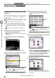
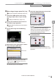
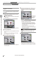

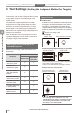

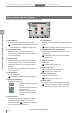

Table Of Contents
- Introduction
- Safety Information for IV Series
- Important Instructions
- Precautions on Regulations and Standards
- Version of the IV Series
- Structure of This Manual
- Contents
- Chapter 1 Getting Started
- Chapter 2 Installation and Connection
- Mounting the Sensor
- Mounting the Monitor
- Cables
- Chapter 3 Basic Operation
- Overview of Screen and Operation
- Basic Operation Flow
- Operation when the Power is Turned on
- Setting to the Factory Default
- Basic Operation for the Monitor
- Chapter 4 Settings Navigator (Setting the Judgment Condition)
- Settings Navigator
- Basic Operation of the Settings Navigator
- 1. Image Optimization (Clearly Image a Target)
- 2. Master Registration (Registering an Image as a Reference for Judgment)
- 3. Tool Settings (Setting the Judgment Method for Targets)
- 4. Output Assignment (Setting Details of Outputting to Output Line)
- Display Method of Extended Functions Menus
- Chapter 5 Operating/Adjusting
- Starting an Operation
- Overview of the Operation Screen
- Names and Functions of the Operation Screen
- Adjusting Thresholds for Judgment
- Tool Auto Tuning (Automatically Adjusting the Judgment Condition)
- Operation flow for the Tool Auto Tuning
- Starting and finishing the Tool Auto Tuning
- Registering the OK/NG images to be used for the Tool Auto Tuning
- Confirming or deleting the images registered for the Tool Auto Tuning
- Tool Auto Tuning by the previous registration information
- Tool Auto Tuning by the registration information file
- Stabilizing the Judgment Process
- Stabilizing the judgment process by taking a clear image of the target
- Imaging the target widely
- Correcting the distorted images due to the installation
- Achieving adequate image brightness
- Achieving good focus
- Reducing the image blur
- Reducing the shininess of the glossy or metal surface
- Adjusting the color tint (for color type only)
- Reducing the effect of illumination variation
- Stabilizing by correcting the misaligned target position
- Stabilizing the position adjustment
- Stabilizing the Outline tool
- ■Basic adjustments
- ■If the outline cannot be detected when the target becomes out of position
- ■If the detection becomes unstable due to the effect of the unwanted outline other than the target
- ■If the target tilts and the outline cannot be detected
- ■If the match rate difference between the high and low-quality-targets is small
- ■If the outline of the target cannot be detected
- Stabilizing the Color Area/Area tool
- Stabilizing the judgment process by taking a clear image of the target
- Shortening the Processing Time
- Chapter 6 Useful Features/Various Functions
- List of the Useful Features
- Displaying the Sensor Setup Menu Screen
- Changeover for a Target (Program Functions)
- Sensor Image History (Confirming the Images whose Status Result is NG)
- Saving the Sensor Settings and Images to a USB Memory
- Setting the Extended Functions of the Sensor
- Setting the Advanced Monitor Information
- Chapter 7 Controlling with Input/Output Line
- Chapter 8 Specifications
- Appendices
- Status Table
- Matching Rate of the Outline Tool and Position Adjustment Tool
- Settings List
- Troubleshooting
- Error Messages
- Remedy when the Monitor cannot be Connected with the Sensor
- Initializing the Network Settings (IP Reset Switch)
- Maintenance
- Index

4-30
- IV Series User's Manual (Monitor) -
Main screen for the Tool Settings
This section explains the main screen for the Tool settings.
(9)(8) (10) (11) (12)
(5)
(4)
(2)
(3)
(1)
(6)
(7)
(1)
[Back] button
Returns to the Master Registration screen.
“2. Master Registration (Registering an Image
as a Reference for Judgment)” (Page 4-20)
(2)
[Tool Name] button
Displays a name of the selected tool on the
monitor. From the pull-down menu, the selected
tool can be switched.
(3)
Master image
Displays the master image and tool window. If
a search region is set, the tool window which
indicate the search region (light blue) will be
displayed.
By tapping the tool window, the selected tool
can be switched.
(4)
[Save] button
Saves the settings.
“Finishing the Settings Navigator” (Page 4-5)
(5)
[Image Type] display
Displays an image type.
................ Displays a master image (still
image).
................ Indicates that the monitor is in
the Test mode.
................ Displays an image taken by
the sensor which is currently
imaging.
(6)
[Zoom] button
Switches to the full-screen display and makes it
possible to enlarge an image on the monitor.
For details, refer to “Switching the display to
the full-screen mode” (Page 5-5).
(7)
[View] button
Displays a menu to select the display pattern of
tools.
“Selecting a display method for tools” (Page 5-7)
(8)
Extended functions display button
Displays the extended functions menu for the
Tool Settings.
“Extended functions for the Tool settings”
(Page 4-58)
(9)
[Add Tool] button
Adds tools.
“Adding a tool” (Page 4-31)
(10)
[Edit Tool] button
Edits settings for the selected tool.
“Editing a tool” (Page 4-31)
(11)
[Delete Tool] button
Deletes the selected tool.
“Deleting a tool” (Page 4-31)
(12)
[Next] button
Proceeds to the Output Assignment settings.
“4. Output Assignment (Setting Details of
Outputting to Output Line)” (Page 4-60)
1. Image Optimization 2. Master Registration 3. Tool Settings 4. Output Assignment
4
Settings Navigator (Setting the Judgment Condition)