
User guide

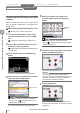
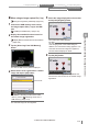
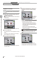

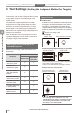

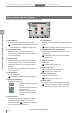
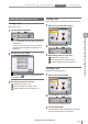

Table Of Contents
- Introduction
- Safety Information for IV Series
- Important Instructions
- Precautions on Regulations and Standards
- Version of the IV Series
- Structure of This Manual
- Contents
- Chapter 1 Getting Started
- Chapter 2 Installation and Connection
- Mounting the Sensor
- Mounting the Monitor
- Cables
- Chapter 3 Basic Operation
- Overview of Screen and Operation
- Basic Operation Flow
- Operation when the Power is Turned on
- Setting to the Factory Default
- Basic Operation for the Monitor
- Chapter 4 Settings Navigator (Setting the Judgment Condition)
- Settings Navigator
- Basic Operation of the Settings Navigator
- 1. Image Optimization (Clearly Image a Target)
- 2. Master Registration (Registering an Image as a Reference for Judgment)
- 3. Tool Settings (Setting the Judgment Method for Targets)
- 4. Output Assignment (Setting Details of Outputting to Output Line)
- Display Method of Extended Functions Menus
- Chapter 5 Operating/Adjusting
- Starting an Operation
- Overview of the Operation Screen
- Names and Functions of the Operation Screen
- Adjusting Thresholds for Judgment
- Tool Auto Tuning (Automatically Adjusting the Judgment Condition)
- Operation flow for the Tool Auto Tuning
- Starting and finishing the Tool Auto Tuning
- Registering the OK/NG images to be used for the Tool Auto Tuning
- Confirming or deleting the images registered for the Tool Auto Tuning
- Tool Auto Tuning by the previous registration information
- Tool Auto Tuning by the registration information file
- Stabilizing the Judgment Process
- Stabilizing the judgment process by taking a clear image of the target
- Imaging the target widely
- Correcting the distorted images due to the installation
- Achieving adequate image brightness
- Achieving good focus
- Reducing the image blur
- Reducing the shininess of the glossy or metal surface
- Adjusting the color tint (for color type only)
- Reducing the effect of illumination variation
- Stabilizing by correcting the misaligned target position
- Stabilizing the position adjustment
- Stabilizing the Outline tool
- ■Basic adjustments
- ■If the outline cannot be detected when the target becomes out of position
- ■If the detection becomes unstable due to the effect of the unwanted outline other than the target
- ■If the target tilts and the outline cannot be detected
- ■If the match rate difference between the high and low-quality-targets is small
- ■If the outline of the target cannot be detected
- Stabilizing the Color Area/Area tool
- Stabilizing the judgment process by taking a clear image of the target
- Shortening the Processing Time
- Chapter 6 Useful Features/Various Functions
- List of the Useful Features
- Displaying the Sensor Setup Menu Screen
- Changeover for a Target (Program Functions)
- Sensor Image History (Confirming the Images whose Status Result is NG)
- Saving the Sensor Settings and Images to a USB Memory
- Setting the Extended Functions of the Sensor
- Setting the Advanced Monitor Information
- Chapter 7 Controlling with Input/Output Line
- Chapter 8 Specifications
- Appendices
- Status Table
- Matching Rate of the Outline Tool and Position Adjustment Tool
- Settings List
- Troubleshooting
- Error Messages
- Remedy when the Monitor cannot be Connected with the Sensor
- Initializing the Network Settings (IP Reset Switch)
- Maintenance
- Index

4-28
- IV Series User's Manual (Monitor) -
In this section, set the tool to judge whether a target
is high-quality-target or low-quality-target in the
master image.
The aspects of a target registered as a master
image are set as a high-quality-target. During an
operation, the sensor judges whether it is a high-
quality-target or low-quality-target by judging the
differences in the registered high-quality-target and
a target to be examined.
Up to 16 detection tools in one program and up to
1 position adjustment tool can be set. Those tools
can judge a target at the same time.
Selecting a tool according to its
intended purpose
Select a tool according to with the purpose of an
examination.
Purposes
Detection tool to be used
Outline tool
Color Area/
Area tool
To detect the surface/
rear face of parts
To detect the
orientation of parts
-
To detect mixture of
parts with different
shapes
-
To detect assembly
deciencies of parts
To detect processing
defects of parts
To detect differences
in sizes (areas)
-
To detect mixture of
different colors
-
Types of tools
Outline tool
A detection tool to calculate the matching rate for
the target to be examined based on the outline
information of a registered high-quality-target.
Judges whether a target is a high or low-quality-
product by setting the threshold to the matching
rate.
“Outline tool” (Page 4-32)
Tool settings
Master image
Outline extraction processing
Processing and judgment during an operation
Internal processing <Judge is OK>
Searches a target which has the outline of same shapes
as an outline of a high-quality-target.
Outline can be detected even if a target is rotated.
Example when the result was NG
No same shapes exist
(Detection of existence)
Different shape
(Shape detection)
Different direction
(Detection of direction)
The matching rate is indicated in 0 to 100.
100 indicates that an outline is completely matched.
The matching rate decreases in accordance with
the number of non-matched parts.
3. Tool Settings
(Setting the Judgment Method for Targets)
1. Image Optimization 2. Master Registration 3. Tool Settings 4. Output Assignment
4
Settings Navigator (Setting the Judgment Condition)