
User guide
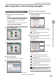

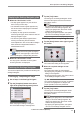
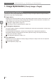


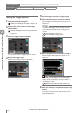
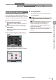
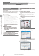
Table Of Contents
- Introduction
- Safety Information for IV Series
- Important Instructions
- Precautions on Regulations and Standards
- Version of the IV Series
- Structure of This Manual
- Contents
- Chapter 1 Getting Started
- Chapter 2 Installation and Connection
- Mounting the Sensor
- Mounting the Monitor
- Cables
- Chapter 3 Basic Operation
- Overview of Screen and Operation
- Basic Operation Flow
- Operation when the Power is Turned on
- Setting to the Factory Default
- Basic Operation for the Monitor
- Chapter 4 Settings Navigator (Setting the Judgment Condition)
- Settings Navigator
- Basic Operation of the Settings Navigator
- 1. Image Optimization (Clearly Image a Target)
- 2. Master Registration (Registering an Image as a Reference for Judgment)
- 3. Tool Settings (Setting the Judgment Method for Targets)
- 4. Output Assignment (Setting Details of Outputting to Output Line)
- Display Method of Extended Functions Menus
- Chapter 5 Operating/Adjusting
- Starting an Operation
- Overview of the Operation Screen
- Names and Functions of the Operation Screen
- Adjusting Thresholds for Judgment
- Tool Auto Tuning (Automatically Adjusting the Judgment Condition)
- Operation flow for the Tool Auto Tuning
- Starting and finishing the Tool Auto Tuning
- Registering the OK/NG images to be used for the Tool Auto Tuning
- Confirming or deleting the images registered for the Tool Auto Tuning
- Tool Auto Tuning by the previous registration information
- Tool Auto Tuning by the registration information file
- Stabilizing the Judgment Process
- Stabilizing the judgment process by taking a clear image of the target
- Imaging the target widely
- Correcting the distorted images due to the installation
- Achieving adequate image brightness
- Achieving good focus
- Reducing the image blur
- Reducing the shininess of the glossy or metal surface
- Adjusting the color tint (for color type only)
- Reducing the effect of illumination variation
- Stabilizing by correcting the misaligned target position
- Stabilizing the position adjustment
- Stabilizing the Outline tool
- ■Basic adjustments
- ■If the outline cannot be detected when the target becomes out of position
- ■If the detection becomes unstable due to the effect of the unwanted outline other than the target
- ■If the target tilts and the outline cannot be detected
- ■If the match rate difference between the high and low-quality-targets is small
- ■If the outline of the target cannot be detected
- Stabilizing the Color Area/Area tool
- Stabilizing the judgment process by taking a clear image of the target
- Shortening the Processing Time
- Chapter 6 Useful Features/Various Functions
- List of the Useful Features
- Displaying the Sensor Setup Menu Screen
- Changeover for a Target (Program Functions)
- Sensor Image History (Confirming the Images whose Status Result is NG)
- Saving the Sensor Settings and Images to a USB Memory
- Setting the Extended Functions of the Sensor
- Setting the Advanced Monitor Information
- Chapter 7 Controlling with Input/Output Line
- Chapter 8 Specifications
- Appendices
- Status Table
- Matching Rate of the Outline Tool and Position Adjustment Tool
- Settings List
- Troubleshooting
- Error Messages
- Remedy when the Monitor cannot be Connected with the Sensor
- Initializing the Network Settings (IP Reset Switch)
- Maintenance
- Index

4-8
- IV Series User's Manual (Monitor) -
Setting the Trigger Options
A trigger in this manual indicates the timing to start imaging with the built-in camera of the sensor. In the
Trigger Options, set the timing to image a target within the eld of view of this device. This device can
image a target at any timing, and can image continuously.
Settings for the Trigger Options
Items Description Setting range
Default
value
Trigger
(Trigger type)
Select the type of the timing to
start imaging.
Internal
Starts imaging continuously within
the time interval specied in the
trigger interval setting.
External
Starts imaging with the external
trigger synchronized with the
target's motion from a photoelectric
sensor or PLC installed outside.
The time (trigger delay) between
inputting the trigger until imaging
starts can be set.
Internal
Trigger interval
Set when the [Internal] is
selected in the trigger type
setting.
Set an interval (cycle) to
automatically start imaging.
1 to 10000 ms 50 ms
Trigger Delay
Set when the [External] is
selected in the trigger type
setting.
Used when the output timing
of the sensor for the trigger
occurrence and the imaging
timing of this device cannot be
synchronized.
This device starts imaging after
the time set in the trigger delay
of the trigger input passes.
0 to 1000 ms 0 ms
Trigger Options Auto Brightness Adjustment Focus Adjustment Extended functions
1. Image Optimization 2. Master Registration 3. Tool Settings 4. Output Assignment
4
Settings Navigator (Setting the Judgment Condition)