
User guide

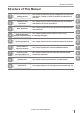
Table Of Contents
- Introduction
- Safety Information for IV Series
- Important Instructions
- Precautions on Regulations and Standards
- Version of the IV Series
- Structure of This Manual
- Contents
- Chapter 1 Getting Started
- Chapter 2 Installation and Connection
- Mounting the Sensor
- Mounting the Monitor
- Cables
- Chapter 3 Basic Operation
- Overview of Screen and Operation
- Basic Operation Flow
- Operation when the Power is Turned on
- Setting to the Factory Default
- Basic Operation for the Monitor
- Chapter 4 Settings Navigator (Setting the Judgment Condition)
- Settings Navigator
- Basic Operation of the Settings Navigator
- 1. Image Optimization (Clearly Image a Target)
- 2. Master Registration (Registering an Image as a Reference for Judgment)
- 3. Tool Settings (Setting the Judgment Method for Targets)
- 4. Output Assignment (Setting Details of Outputting to Output Line)
- Display Method of Extended Functions Menus
- Chapter 5 Operating/Adjusting
- Starting an Operation
- Overview of the Operation Screen
- Names and Functions of the Operation Screen
- Adjusting Thresholds for Judgment
- Tool Auto Tuning (Automatically Adjusting the Judgment Condition)
- Operation flow for the Tool Auto Tuning
- Starting and finishing the Tool Auto Tuning
- Registering the OK/NG images to be used for the Tool Auto Tuning
- Confirming or deleting the images registered for the Tool Auto Tuning
- Tool Auto Tuning by the previous registration information
- Tool Auto Tuning by the registration information file
- Stabilizing the Judgment Process
- Stabilizing the judgment process by taking a clear image of the target
- Imaging the target widely
- Correcting the distorted images due to the installation
- Achieving adequate image brightness
- Achieving good focus
- Reducing the image blur
- Reducing the shininess of the glossy or metal surface
- Adjusting the color tint (for color type only)
- Reducing the effect of illumination variation
- Stabilizing by correcting the misaligned target position
- Stabilizing the position adjustment
- Stabilizing the Outline tool
- ■Basic adjustments
- ■If the outline cannot be detected when the target becomes out of position
- ■If the detection becomes unstable due to the effect of the unwanted outline other than the target
- ■If the target tilts and the outline cannot be detected
- ■If the match rate difference between the high and low-quality-targets is small
- ■If the outline of the target cannot be detected
- Stabilizing the Color Area/Area tool
- Stabilizing the judgment process by taking a clear image of the target
- Shortening the Processing Time
- Chapter 6 Useful Features/Various Functions
- List of the Useful Features
- Displaying the Sensor Setup Menu Screen
- Changeover for a Target (Program Functions)
- Sensor Image History (Confirming the Images whose Status Result is NG)
- Saving the Sensor Settings and Images to a USB Memory
- Setting the Extended Functions of the Sensor
- Setting the Advanced Monitor Information
- Chapter 7 Controlling with Input/Output Line
- Chapter 8 Specifications
- Appendices
- Status Table
- Matching Rate of the Outline Tool and Position Adjustment Tool
- Settings List
- Troubleshooting
- Error Messages
- Remedy when the Monitor cannot be Connected with the Sensor
- Initializing the Network Settings (IP Reset Switch)
- Maintenance
- Index

3
- IV Series User's Manual (Monitor) -
Important Instructions
Measures to be taken when an abnormality occurs
In the following cases, turn the power OFF immediately. Using the IV Series in an abnormal condition
could cause re, electric shock, or malfunction.
Contact our ofce for repair.
If water or debris enters the IV Series.
If the IV Series is dropped or the case is damaged.
If abnormal smoke or odor emanates from the IV Series.
Precautions on installation
To use this product correctly and safely, avoid installing it in the following locations. Failure to
do so may cause re, electric shock, or malfunction.
Outdoors
Altitude above 2000 m
Locations that are humid, dusty or poorly ventilated
Locations where the temperature is high such as those exposed to direct sunlight
Locations where there are ammable or corrosive gases
Locations where the unit may be directly subjected to vibration or impact
Locations where water, oil, or chemicals may splash onto the unit
To improve the anti-noise feature, install the unit following the precautions below. Otherwise, a
malfunction may occur.
Mount the sensor onto the insulated attached mounting adapter.
Ground the FG cable (drain cable) of the sensor.
Do not mount the unit in a cabinet where high-voltage equipment is already installed.
Mount the unit as far from power lines as possible.
Separate the unit as far as possible from the devices that emit strong electric or magnetic
eld (such as solenoid or chopper).
Separate the I/O signal line from the power line or high-voltage line.
For power supply
Noise superimposed on the power supply could cause malfunction. Use a stabilized DC
power supply congured with an isolation transformer.
When using a commercially available switching regulator, be sure to ground the frame ground
terminal.
Devices including this unit are precision components. Do not apply shock or vibration.
When connecting to a network, let engineers who are knowledgeable about networks handle it.