
User guide


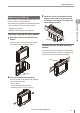
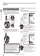
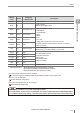
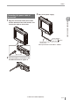

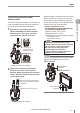
Table Of Contents
- Introduction
- Safety Information for IV Series
- Important Instructions
- Precautions on Regulations and Standards
- Version of the IV Series
- Structure of This Manual
- Contents
- Chapter 1 Getting Started
- Chapter 2 Installation and Connection
- Mounting the Sensor
- Mounting the Monitor
- Cables
- Chapter 3 Basic Operation
- Overview of Screen and Operation
- Basic Operation Flow
- Operation when the Power is Turned on
- Setting to the Factory Default
- Basic Operation for the Monitor
- Chapter 4 Settings Navigator (Setting the Judgment Condition)
- Settings Navigator
- Basic Operation of the Settings Navigator
- 1. Image Optimization (Clearly Image a Target)
- 2. Master Registration (Registering an Image as a Reference for Judgment)
- 3. Tool Settings (Setting the Judgment Method for Targets)
- 4. Output Assignment (Setting Details of Outputting to Output Line)
- Display Method of Extended Functions Menus
- Chapter 5 Operating/Adjusting
- Starting an Operation
- Overview of the Operation Screen
- Names and Functions of the Operation Screen
- Adjusting Thresholds for Judgment
- Tool Auto Tuning (Automatically Adjusting the Judgment Condition)
- Operation flow for the Tool Auto Tuning
- Starting and finishing the Tool Auto Tuning
- Registering the OK/NG images to be used for the Tool Auto Tuning
- Confirming or deleting the images registered for the Tool Auto Tuning
- Tool Auto Tuning by the previous registration information
- Tool Auto Tuning by the registration information file
- Stabilizing the Judgment Process
- Stabilizing the judgment process by taking a clear image of the target
- Imaging the target widely
- Correcting the distorted images due to the installation
- Achieving adequate image brightness
- Achieving good focus
- Reducing the image blur
- Reducing the shininess of the glossy or metal surface
- Adjusting the color tint (for color type only)
- Reducing the effect of illumination variation
- Stabilizing by correcting the misaligned target position
- Stabilizing the position adjustment
- Stabilizing the Outline tool
- ■Basic adjustments
- ■If the outline cannot be detected when the target becomes out of position
- ■If the detection becomes unstable due to the effect of the unwanted outline other than the target
- ■If the target tilts and the outline cannot be detected
- ■If the match rate difference between the high and low-quality-targets is small
- ■If the outline of the target cannot be detected
- Stabilizing the Color Area/Area tool
- Stabilizing the judgment process by taking a clear image of the target
- Shortening the Processing Time
- Chapter 6 Useful Features/Various Functions
- List of the Useful Features
- Displaying the Sensor Setup Menu Screen
- Changeover for a Target (Program Functions)
- Sensor Image History (Confirming the Images whose Status Result is NG)
- Saving the Sensor Settings and Images to a USB Memory
- Setting the Extended Functions of the Sensor
- Setting the Advanced Monitor Information
- Chapter 7 Controlling with Input/Output Line
- Chapter 8 Specifications
- Appendices
- Status Table
- Matching Rate of the Outline Tool and Position Adjustment Tool
- Settings List
- Troubleshooting
- Error Messages
- Remedy when the Monitor cannot be Connected with the Sensor
- Initializing the Network Settings (IP Reset Switch)
- Maintenance
- Index

2-12
- IV Series User's Manual (Monitor) -
Cables
Connecting the power I/O cable of
the sensor
1
Adjust the pins of the connector for the
power I/O cable and pin connection of the
cable connector, and connect the cable to
the sensor.
Adjust the pins and the
pin connection
2
Tighten the connector by turning the screw-
on connector in the clockwise direction.
Tightening torque of the screws needs to be 1.0
to 1.5 N·m.
When connecting the connector, insert it
without tipping and tighten it well. If the
tightening is weak, vibration can loosen
the connector and cause bad connections.
Also, the enclosure rating may not be
maintained with loose connection.
* Indication is retighten approximately
90° to 120° with tools such as pliers
after tightening with hands.
3
Wire each cable according to its intended
purpose.
Selecting NPN output
When NPN is selected in the Polarity (Page 3-11)
DC24V
IN
OUT
(NPN)
Black/White/
Gray/Orange
(OUT)
Brown (DC24V)
Black (OUT1) / White (OUT2) /
Gray (OUT3) / Orange (OUT4)
Pink (IN1 : External trigger) / Yellow (IN2) /
Light Blue (IN3) / Purple (IN4) /
Green (IN5) / Red (IN6)
Use it by assigning the optional function
to OUT1 to OUT4 and IN2 to IN6.
External device
Load
Blue (0V)
Drain wire (FG)
Pink/Yellow/
Light Blue/Purple/
Green/Red
(IN)
Selecting PNP output
When PNP is selected in the Polarity (Page 3-11)
DC24V
IN
OUT
(PNP)
Black/White/
Gray/Orange
(OUT)
Brown (DC24V)
Black (OUT1) / White (OUT2) /
Gray (OUT3) / Orange (OUT4)
Pink (IN1 : External trigger) / Yellow (IN2) /
Light Blue (IN3) / Purple (IN4) /
Green (IN5) / Red (IN6)
Use it by assigning the optional function
to OUT1 to OUT4 and IN2 to IN6.
External device
Load
Blue (0V)
Drain wire (FG)
Pink/Yellow/
Light Blue/Purple/
Green/Red
(IN)
Cables
2
Installation and Connection