
User guide


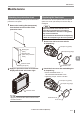


Table Of Contents
- Introduction
- Safety Information for IV Series
- Important Instructions
- Precautions on Regulations and Standards
- Version of the IV Series
- Structure of This Manual
- Contents
- Chapter 1 Getting Started
- Chapter 2 Installation and Connection
- Mounting the Sensor
- Mounting the Monitor
- Cables
- Chapter 3 Basic Operation
- Overview of Screen and Operation
- Basic Operation Flow
- Operation when the Power is Turned on
- Setting to the Factory Default
- Basic Operation for the Monitor
- Chapter 4 Settings Navigator (Setting the Judgment Condition)
- Settings Navigator
- Basic Operation of the Settings Navigator
- 1. Image Optimization (Clearly Image a Target)
- 2. Master Registration (Registering an Image as a Reference for Judgment)
- 3. Tool Settings (Setting the Judgment Method for Targets)
- 4. Output Assignment (Setting Details of Outputting to Output Line)
- Display Method of Extended Functions Menus
- Chapter 5 Operating/Adjusting
- Starting an Operation
- Overview of the Operation Screen
- Names and Functions of the Operation Screen
- Adjusting Thresholds for Judgment
- Tool Auto Tuning (Automatically Adjusting the Judgment Condition)
- Operation flow for the Tool Auto Tuning
- Starting and finishing the Tool Auto Tuning
- Registering the OK/NG images to be used for the Tool Auto Tuning
- Confirming or deleting the images registered for the Tool Auto Tuning
- Tool Auto Tuning by the previous registration information
- Tool Auto Tuning by the registration information file
- Stabilizing the Judgment Process
- Stabilizing the judgment process by taking a clear image of the target
- Imaging the target widely
- Correcting the distorted images due to the installation
- Achieving adequate image brightness
- Achieving good focus
- Reducing the image blur
- Reducing the shininess of the glossy or metal surface
- Adjusting the color tint (for color type only)
- Reducing the effect of illumination variation
- Stabilizing by correcting the misaligned target position
- Stabilizing the position adjustment
- Stabilizing the Outline tool
- ■Basic adjustments
- ■If the outline cannot be detected when the target becomes out of position
- ■If the detection becomes unstable due to the effect of the unwanted outline other than the target
- ■If the target tilts and the outline cannot be detected
- ■If the match rate difference between the high and low-quality-targets is small
- ■If the outline of the target cannot be detected
- Stabilizing the Color Area/Area tool
- Stabilizing the judgment process by taking a clear image of the target
- Shortening the Processing Time
- Chapter 6 Useful Features/Various Functions
- List of the Useful Features
- Displaying the Sensor Setup Menu Screen
- Changeover for a Target (Program Functions)
- Sensor Image History (Confirming the Images whose Status Result is NG)
- Saving the Sensor Settings and Images to a USB Memory
- Setting the Extended Functions of the Sensor
- Setting the Advanced Monitor Information
- Chapter 7 Controlling with Input/Output Line
- Chapter 8 Specifications
- Appendices
- Status Table
- Matching Rate of the Outline Tool and Position Adjustment Tool
- Settings List
- Troubleshooting
- Error Messages
- Remedy when the Monitor cannot be Connected with the Sensor
- Initializing the Network Settings (IP Reset Switch)
- Maintenance
- Index

A-44
- IV Series User's Manual (Monitor) -
A
Index
Intelligent Monitor ............................. 1-10, 8-4, 8-10
Internal trigger .....................................................7-3
I/O Monitor .........................................................6-28
I/O Settings ........................................................6-26
Items of extended functions for the Image
Optimization.......................................................4-16
Items of extended functions for the Master
Registration .......................................................4-22
Items of extended functions for
the Tool settings .................................................4-58
IV Series ..............................................................1-4
J
Judgment processing ow ...................................1-6
L
Language...........................................................6-51
Lighting ..............................................................4-18
LINK/ACT (link/activity) indicator light .............. A-32
List of the Useful Features...................................6-2
Loading and conrming the saved images ........6-15
Logic Settings ....................................................4-63
M
Main screen for the Image Optimization ..............4-7
Main screen for the Master Registration............4-20
Main screen for the Output Assignment ............4-60
Main screen for the Tool Settings ......................4-30
Maintenance ..................................................... A-41
Mask settings.....................................................4-45
Master image registration from
the image history in the sensor..........................4-22
Matching rate at the time of protrusion ............... A-5
Matching Rate of the Outline Tool and
Position Adjustment Tool .................................... A-5
Menu Screen .......................................................5-4
Monitor...............................................................1-15
Monitor cable .....................................................8-13
Monitor cable (M12 4pin - M12 4pin) .................1-12
Monitor Device Settings.....................................6-45
Monitor Environment .........................................6-45
Monitor Information............................................6-53
Monitor power cable ..........................................8-12
Monitor power cable (M8 4pin - strand wire) .....1-10
Monitor Settings.................................................6-45
Monitor Settings screen ...................................... A-9
Mounting adapter......................................... 1-9, 8-8
Mounting the attachment .....................................2-6
Mounting the dome attachment ...........................2-6
Mounting the Monitor ...........................................2-8
Mounting the mounting adapter ...........................2-4
Mounting from the jig side ..............................2-4
Mounting on the wall ......................................2-4
Mounting the sensor ............................................2-4
Mounting the Sensor ...........................................2-2
Mounting the sensor onto the mounting adapter
...2-4
Mounting to a panel ...........................................2-10
Mounting to a wall................................................2-8
Mounting to the DIN rail ..................................... 2-11
Mounting using DIN mounting adapter ..............2-11
Mounting with the wall mounting adapter ............2-8
N
Name and Function of Each Part ......................1-13
Name and function of each part of the sensor...1-13
Names and Functions of the Operation Screen
.....5-4
Network Settings ..................................... 6-31, 6-48
No-voltage input
(When the NPN output is selected) ...................2-14
O
Operating in the shortest cycle ............................7-3
Operation ow for the Tool Auto Tuning .............5-16
Operation ow when the power is turned on .......3-5
Operation for initial startup of the monitor
(Direct Connection)..............................................3-6
Operation for initial startup of the monitor
(Network Connection) ..........................................3-7
Operation for initial startup of the sensor...........3-11
Operation of the indicator light...........................1-14
Operations when Power of the Sensor is
Turned on ..........................................................7-11
Operation when the Power is Turned on .............3-5
Optional parts for the monitor .................. 1-10, 8-12
Optional parts for the sensor ....................... 1-8, 8-7
Other methods of conrming
a network connection........................................ A-35
Outline tool ........................................................4-32
Output circuit .....................................................2-14
Output Settings ..................................................6-27
Overview of IV Series ..........................................1-4
Overview of Screen and Operation .....................3-2
Overview of the Operation Screen ......................5-3
Overview of the program functions ......................6-8