
User guide
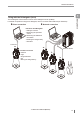

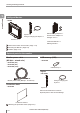

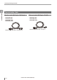
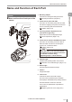

Table Of Contents
- Introduction
- Safety Information for IV Series
- Important Instructions
- Precautions on Regulations and Standards
- Version of the IV Series
- Structure of This Manual
- Contents
- Chapter 1 Getting Started
- Chapter 2 Installation and Connection
- Mounting the Sensor
- Mounting the Monitor
- Cables
- Chapter 3 Basic Operation
- Overview of Screen and Operation
- Basic Operation Flow
- Operation when the Power is Turned on
- Setting to the Factory Default
- Basic Operation for the Monitor
- Chapter 4 Settings Navigator (Setting the Judgment Condition)
- Settings Navigator
- Basic Operation of the Settings Navigator
- 1. Image Optimization (Clearly Image a Target)
- 2. Master Registration (Registering an Image as a Reference for Judgment)
- 3. Tool Settings (Setting the Judgment Method for Targets)
- 4. Output Assignment (Setting Details of Outputting to Output Line)
- Display Method of Extended Functions Menus
- Chapter 5 Operating/Adjusting
- Starting an Operation
- Overview of the Operation Screen
- Names and Functions of the Operation Screen
- Adjusting Thresholds for Judgment
- Tool Auto Tuning (Automatically Adjusting the Judgment Condition)
- Operation flow for the Tool Auto Tuning
- Starting and finishing the Tool Auto Tuning
- Registering the OK/NG images to be used for the Tool Auto Tuning
- Confirming or deleting the images registered for the Tool Auto Tuning
- Tool Auto Tuning by the previous registration information
- Tool Auto Tuning by the registration information file
- Stabilizing the Judgment Process
- Stabilizing the judgment process by taking a clear image of the target
- Imaging the target widely
- Correcting the distorted images due to the installation
- Achieving adequate image brightness
- Achieving good focus
- Reducing the image blur
- Reducing the shininess of the glossy or metal surface
- Adjusting the color tint (for color type only)
- Reducing the effect of illumination variation
- Stabilizing by correcting the misaligned target position
- Stabilizing the position adjustment
- Stabilizing the Outline tool
- ■Basic adjustments
- ■If the outline cannot be detected when the target becomes out of position
- ■If the detection becomes unstable due to the effect of the unwanted outline other than the target
- ■If the target tilts and the outline cannot be detected
- ■If the match rate difference between the high and low-quality-targets is small
- ■If the outline of the target cannot be detected
- Stabilizing the Color Area/Area tool
- Stabilizing the judgment process by taking a clear image of the target
- Shortening the Processing Time
- Chapter 6 Useful Features/Various Functions
- List of the Useful Features
- Displaying the Sensor Setup Menu Screen
- Changeover for a Target (Program Functions)
- Sensor Image History (Confirming the Images whose Status Result is NG)
- Saving the Sensor Settings and Images to a USB Memory
- Setting the Extended Functions of the Sensor
- Setting the Advanced Monitor Information
- Chapter 7 Controlling with Input/Output Line
- Chapter 8 Specifications
- Appendices
- Status Table
- Matching Rate of the Outline Tool and Position Adjustment Tool
- Settings List
- Troubleshooting
- Error Messages
- Remedy when the Monitor cannot be Connected with the Sensor
- Initializing the Network Settings (IP Reset Switch)
- Maintenance
- Index

1-14
- IV Series User's Manual (Monitor) -
Name and Function of Each Part
Operation of the indicator light
Details on operations of the indicator light are
shown below.
1 2 3
4 5
1 PWR/ERR
Indicates the power supplying status to the
sensor and the error status of the sensor.
Green (ON) ...... Operating.
Green (Blink) .... Setting processing. Operation
is stopped. Blinks once a
second.
Red (ON) .......... Unrecoverable error has
occurred.
Red (Blink) ....... Recoverable error has
occurred.
(OFF) ............... Power is not supplied.
Adjusting the focusing position
(
manual focus only).
For countermeasures when an error occurred,
refer to “Error Messages” (Page A-22).
2 OUT
Indicates the comprehensive result.
Green ...............
Comprehensive result is “OK”.
Red ..................
Comprehensive result is “NG”.
(OFF) ............... Setting processing.
Standby status until the rst
judge nishes after starting the
operation or after switching
the program number.
Orange (Blink) ..
Indicates the focusing status
while adjusting the focusing
position with the blinking speed
(manual focus type only).
“Focus adjustment for
the manual focusing type”
(Page 4-14)
3 TRIG
Green light lights up (one-shot) according to
input of the internal or external trigger.
4 STATUS
Indicates the connection status within the monitor.
Green (ON) ...... Normally connected with
monitor.
Green (Blink) .... IP address has been retrieved
but the sensor is not correctly
connected with monitor.
(OFF) ............... IP address is not assigned.
Sensor is not correctly
connected with monitor.
Orange (Blink) ..
Indicates the focusing status
while adjusting the focusing
position with the blinking speed
(manual focus type only).
“Focus adjustment for the
manual focusing type” (Page 4-14)
When the sensor cannot correctly connect with
the monitor, refer to “Remedy when the
Monitor cannot be Connected with the Sensor”
(Page A-28).
5 LINK/ACT
Indicates the linking status within monitor or
Ethernet switch.
Green (ON) ...... Normally linked.
Green (Blink) .... Normally linked, and the data
is sending/receiving.
(OFF) ...............
Sensor is not normally linked.
1
Getting Started