
User guide


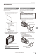
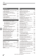


Table Of Contents
- Introduction
- Safety Information for IV Series
- Important Instructions
- Precautions on Regulations and Standards
- Version of the IV Series
- Structure of This Manual
- Contents
- Chapter 1 Getting Started
- Chapter 2 Installation and Connection
- Mounting the Sensor
- Mounting the Monitor
- Cables
- Chapter 3 Basic Operation
- Overview of Screen and Operation
- Basic Operation Flow
- Operation when the Power is Turned on
- Setting to the Factory Default
- Basic Operation for the Monitor
- Chapter 4 Settings Navigator (Setting the Judgment Condition)
- Settings Navigator
- Basic Operation of the Settings Navigator
- 1. Image Optimization (Clearly Image a Target)
- 2. Master Registration (Registering an Image as a Reference for Judgment)
- 3. Tool Settings (Setting the Judgment Method for Targets)
- 4. Output Assignment (Setting Details of Outputting to Output Line)
- Display Method of Extended Functions Menus
- Chapter 5 Operating/Adjusting
- Starting an Operation
- Overview of the Operation Screen
- Names and Functions of the Operation Screen
- Adjusting Thresholds for Judgment
- Tool Auto Tuning (Automatically Adjusting the Judgment Condition)
- Operation flow for the Tool Auto Tuning
- Starting and finishing the Tool Auto Tuning
- Registering the OK/NG images to be used for the Tool Auto Tuning
- Confirming or deleting the images registered for the Tool Auto Tuning
- Tool Auto Tuning by the previous registration information
- Tool Auto Tuning by the registration information file
- Stabilizing the Judgment Process
- Stabilizing the judgment process by taking a clear image of the target
- Imaging the target widely
- Correcting the distorted images due to the installation
- Achieving adequate image brightness
- Achieving good focus
- Reducing the image blur
- Reducing the shininess of the glossy or metal surface
- Adjusting the color tint (for color type only)
- Reducing the effect of illumination variation
- Stabilizing by correcting the misaligned target position
- Stabilizing the position adjustment
- Stabilizing the Outline tool
- ■Basic adjustments
- ■If the outline cannot be detected when the target becomes out of position
- ■If the detection becomes unstable due to the effect of the unwanted outline other than the target
- ■If the target tilts and the outline cannot be detected
- ■If the match rate difference between the high and low-quality-targets is small
- ■If the outline of the target cannot be detected
- Stabilizing the Color Area/Area tool
- Stabilizing the judgment process by taking a clear image of the target
- Shortening the Processing Time
- Chapter 6 Useful Features/Various Functions
- List of the Useful Features
- Displaying the Sensor Setup Menu Screen
- Changeover for a Target (Program Functions)
- Sensor Image History (Confirming the Images whose Status Result is NG)
- Saving the Sensor Settings and Images to a USB Memory
- Setting the Extended Functions of the Sensor
- Setting the Advanced Monitor Information
- Chapter 7 Controlling with Input/Output Line
- Chapter 8 Specifications
- Appendices
- Status Table
- Matching Rate of the Outline Tool and Position Adjustment Tool
- Settings List
- Troubleshooting
- Error Messages
- Remedy when the Monitor cannot be Connected with the Sensor
- Initializing the Network Settings (IP Reset Switch)
- Maintenance
- Index

A-43
- IV Series User's Manual (Monitor) -
A
Index
D
Default value......................................................4-60
Deleting a tool....................................................4-31
Device name......................................................6-29
Device settings ..................................................6-29
Digital Zoom (monochrome type only)...............4-19
Dimensions ..........................................................8-6
DIN mounting adapter ..............................1-11, 8-12
Displaying and outputting the status result ......... A-4
Displaying and outputting the status result at
the time of position adjustment ........................... A-4
Displaying from the run screen ................ 6-14, 6-18
Displaying from
the Sensor setup menu screen................ 6-14, 6-18
Displaying the histogram ...................................5-12
Displaying the Sensor Image History screen.....6-14
Displaying the Sensor Setup Menu Screen .........6-7
Displaying the Settings Navigator guide ..............4-5
Displaying the statistical information .................5-10
Displaying the USB Memory screen ..................6-18
Display Method of Extended Functions Menus
...4-66
Display methods for tools ....................................5-7
For color type .................................................5-7
For monochrome type ....................................5-8
Display Settings .................................................6-49
Dome attachment ........................................ 1-8, 8-7
E
Editing a program name ....................................6-12
Editing a tool ......................................................4-31
Editing the tool window ......................................3-15
Editing the value with the slider .........................3-14
Enabling the screen capturing function .............6-23
Enlarging the image display ................................5-6
Environmental....................................................6-25
Error Messages ................................................ A-22
Ethernet cable ...................................................8-13
Ethernet cable (M12 4pin - RJ-45) ....................1-12
Exiting the sensor settings and starting an
operation..............................................................5-2
Extended functions for the Image Optimization
...4-16
Extended functions for the Master Registration
...4-22
Extended functions for the Outline tool..............4-37
Extended functions for the Output Assignment
....4-62
Extended functions for
the Position Adjustment tool ..............................4-57
Extended functions for the Tool settings ............4-58
Extended functions items for the Output
Assignment ........................................................4-62
Extended functions of the Color Area/Area tool
...4-48
External trigger ....................................................7-2
F
Field Network.....................................................6-37
Finishing by completing all steps .........................4-5
Finishing the Settings Navigator ..........................4-5
Finishing without completing the step..................4-5
Fixed Reference Area ........................................4-50
Flow in the Settings Navigator .............................4-2
Flow of the internal process...............................5-40
Focus Adjustment ..............................................4-12
Focus adjustment for the auto focusing type .....4-12
Focus adjustment for the manual focusing type
...4-14
Folder composition and le naming rules ..........6-24
For the processing time .....................................5-40
Front cover ..........................................................8-8
Front cover (for replacement) ..............................1-9
FTP ....................................................................6-32
FTP Destination Settings ...................................6-33
H
Hanging on the hook ...........................................2-8
Hiding the histogram..........................................5-13
Hiding the statistical information ........................ 5-11
I
Imaging Area .....................................................4-17
Imaging the target widely...................................5-32
Importing the individual status output of
each detection tool/logic ......................................7-5
Importing the Status Output.................................7-4
Importing the total status output ..........................7-4
Infrared polarization lter attachment ..................1-8
Initialize Monitor.................................................6-53
Initializing a program .........................................6-13
Initializing the monitor ........................................3-13
Initializing the network settings ......................... A-40
Initializing the Network Settings
(IP Reset Switch) .............................................. A-40
Initializing the sensor ............................... 3-12, 6-44
Input circuit ........................................................2-14
Input Response Time.........................................7-12
Description for symbols ...............................7-12
Response time for the error clear input .......7-12
Response time for the external master
registration input ..........................................7-12
Response time for
the switch program input ..............................7-12
Input Settings.....................................................6-26
Inputting characters ...........................................3-16
Installed distance of the dome attachment ..........2-6
Installing/Removing the USB memory ...............6-18
Installing the sensor at an angle ........................5-35
Installing the USB memory ................................6-18