
User guide
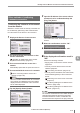


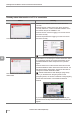


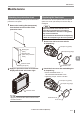
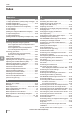


Table Of Contents
- Introduction
- Safety Information for IV Series
- Important Instructions
- Precautions on Regulations and Standards
- Version of the IV Series
- Structure of This Manual
- Contents
- Chapter 1 Getting Started
- Chapter 2 Installation and Connection
- Mounting the Sensor
- Mounting the Monitor
- Cables
- Chapter 3 Basic Operation
- Overview of Screen and Operation
- Basic Operation Flow
- Operation when the Power is Turned on
- Setting to the Factory Default
- Basic Operation for the Monitor
- Chapter 4 Settings Navigator (Setting the Judgment Condition)
- Settings Navigator
- Basic Operation of the Settings Navigator
- 1. Image Optimization (Clearly Image a Target)
- 2. Master Registration (Registering an Image as a Reference for Judgment)
- 3. Tool Settings (Setting the Judgment Method for Targets)
- 4. Output Assignment (Setting Details of Outputting to Output Line)
- Display Method of Extended Functions Menus
- Chapter 5 Operating/Adjusting
- Starting an Operation
- Overview of the Operation Screen
- Names and Functions of the Operation Screen
- Adjusting Thresholds for Judgment
- Tool Auto Tuning (Automatically Adjusting the Judgment Condition)
- Operation flow for the Tool Auto Tuning
- Starting and finishing the Tool Auto Tuning
- Registering the OK/NG images to be used for the Tool Auto Tuning
- Confirming or deleting the images registered for the Tool Auto Tuning
- Tool Auto Tuning by the previous registration information
- Tool Auto Tuning by the registration information file
- Stabilizing the Judgment Process
- Stabilizing the judgment process by taking a clear image of the target
- Imaging the target widely
- Correcting the distorted images due to the installation
- Achieving adequate image brightness
- Achieving good focus
- Reducing the image blur
- Reducing the shininess of the glossy or metal surface
- Adjusting the color tint (for color type only)
- Reducing the effect of illumination variation
- Stabilizing by correcting the misaligned target position
- Stabilizing the position adjustment
- Stabilizing the Outline tool
- ■Basic adjustments
- ■If the outline cannot be detected when the target becomes out of position
- ■If the detection becomes unstable due to the effect of the unwanted outline other than the target
- ■If the target tilts and the outline cannot be detected
- ■If the match rate difference between the high and low-quality-targets is small
- ■If the outline of the target cannot be detected
- Stabilizing the Color Area/Area tool
- Stabilizing the judgment process by taking a clear image of the target
- Shortening the Processing Time
- Chapter 6 Useful Features/Various Functions
- List of the Useful Features
- Displaying the Sensor Setup Menu Screen
- Changeover for a Target (Program Functions)
- Sensor Image History (Confirming the Images whose Status Result is NG)
- Saving the Sensor Settings and Images to a USB Memory
- Setting the Extended Functions of the Sensor
- Setting the Advanced Monitor Information
- Chapter 7 Controlling with Input/Output Line
- Chapter 8 Specifications
- Appendices
- Status Table
- Matching Rate of the Outline Tool and Position Adjustment Tool
- Settings List
- Troubleshooting
- Error Messages
- Remedy when the Monitor cannot be Connected with the Sensor
- Initializing the Network Settings (IP Reset Switch)
- Maintenance
- Index

A-35
- IV Series User's Manual (Monitor) -
A
Remedy when the Monitor cannot be Connected with the Sensor
Other methods of conrming
a network connection
Conrming the existence of the sensor
from the monitor
Whether or not the sensor is correctly connected can
be conrmed by performing a test communication
from the monitor to the sensor to be connected.
1
Displays the Sensor Connect screen.
For the rst startup of the monitor or after
monitor initialization
“Operation for initial startup of the monitor
(Network Connection)” (Page 3-7)
If not connected with the sensor via a
network
Automatically opens after the power is turned on.
If connected with the sensor via a network
“When connecting with the sensor via a
network” (Page 6-46)
When the monitor and the sensor are connected
via a network, the [Network Connection] will be
displayed and the IP address of the connected
sensor will be displayed.
2
Tap the [Specify Sensor] button.
3
Input the IP address of the sensor whose
existence is to be conrmed and tap the
[Ping Test] button.
The conrmation result will be displayed on the
monitor.
When the conrmation result is “OK”
When the conrmation result is “NG”
If the displayed conrmation result is
“NG”
Conrm the following contents.
Supply power to the sensor and the network
equipment.
Correctly connect with the sensor and the
network equipment.
“Connecting via network” (Page 2-16)
Correctly set the IP address, the subnet mask,
and the default gateway of the monitor and
sensor.
“Searching for a sensor to be connected”
(Page 3-8)
“Conrming/Setting the IP address of the
monitor” (Page A-36)
“Conrming/Setting the IP address of the
sensor” (Page A-37)
The existence conrmation function utilizes the ping
command. Note that even when this is executed
for devices other than a sensor, conrmation will
succeed if there is a response to the ping command.