
User guide
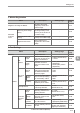

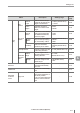
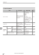


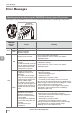

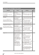
Table Of Contents
- Introduction
- Safety Information for IV Series
- Important Instructions
- Precautions on Regulations and Standards
- Version of the IV Series
- Structure of This Manual
- Contents
- Chapter 1 Getting Started
- Chapter 2 Installation and Connection
- Mounting the Sensor
- Mounting the Monitor
- Cables
- Chapter 3 Basic Operation
- Overview of Screen and Operation
- Basic Operation Flow
- Operation when the Power is Turned on
- Setting to the Factory Default
- Basic Operation for the Monitor
- Chapter 4 Settings Navigator (Setting the Judgment Condition)
- Settings Navigator
- Basic Operation of the Settings Navigator
- 1. Image Optimization (Clearly Image a Target)
- 2. Master Registration (Registering an Image as a Reference for Judgment)
- 3. Tool Settings (Setting the Judgment Method for Targets)
- 4. Output Assignment (Setting Details of Outputting to Output Line)
- Display Method of Extended Functions Menus
- Chapter 5 Operating/Adjusting
- Starting an Operation
- Overview of the Operation Screen
- Names and Functions of the Operation Screen
- Adjusting Thresholds for Judgment
- Tool Auto Tuning (Automatically Adjusting the Judgment Condition)
- Operation flow for the Tool Auto Tuning
- Starting and finishing the Tool Auto Tuning
- Registering the OK/NG images to be used for the Tool Auto Tuning
- Confirming or deleting the images registered for the Tool Auto Tuning
- Tool Auto Tuning by the previous registration information
- Tool Auto Tuning by the registration information file
- Stabilizing the Judgment Process
- Stabilizing the judgment process by taking a clear image of the target
- Imaging the target widely
- Correcting the distorted images due to the installation
- Achieving adequate image brightness
- Achieving good focus
- Reducing the image blur
- Reducing the shininess of the glossy or metal surface
- Adjusting the color tint (for color type only)
- Reducing the effect of illumination variation
- Stabilizing by correcting the misaligned target position
- Stabilizing the position adjustment
- Stabilizing the Outline tool
- ■Basic adjustments
- ■If the outline cannot be detected when the target becomes out of position
- ■If the detection becomes unstable due to the effect of the unwanted outline other than the target
- ■If the target tilts and the outline cannot be detected
- ■If the match rate difference between the high and low-quality-targets is small
- ■If the outline of the target cannot be detected
- Stabilizing the Color Area/Area tool
- Stabilizing the judgment process by taking a clear image of the target
- Shortening the Processing Time
- Chapter 6 Useful Features/Various Functions
- List of the Useful Features
- Displaying the Sensor Setup Menu Screen
- Changeover for a Target (Program Functions)
- Sensor Image History (Confirming the Images whose Status Result is NG)
- Saving the Sensor Settings and Images to a USB Memory
- Setting the Extended Functions of the Sensor
- Setting the Advanced Monitor Information
- Chapter 7 Controlling with Input/Output Line
- Chapter 8 Specifications
- Appendices
- Status Table
- Matching Rate of the Outline Tool and Position Adjustment Tool
- Settings List
- Troubleshooting
- Error Messages
- Remedy when the Monitor cannot be Connected with the Sensor
- Initializing the Network Settings (IP Reset Switch)
- Maintenance
- Index

A-23
- IV Series User's Manual (Monitor) -
A
Error Messages
PWR/ERR
indicator
status
Cause Remedy
Red Blink
The external master image
registration error (with
registered master image)
occurred. The following
errors occurred even though
the image was updated and
registered as a master image.
For the new master image,
the outline cannot be
extracted with the outline
tool.
For the new master image,
the area cannot be extracted
with the color area/area tool.
An external master image registration error can be
xed using one of the following procedures.
Successful next external master image registration
Clearing the Error input
Switching the program number
Proceeding to the settings screen of the sensor
Checking that the image to be registered and the
detection tools/position adjustment settings are
applicable.
An FTP error occurred. The
following errors occurred.
Connection with the FTP
server failed.
Tranfer to the transfer
destination folder failed.
The transfer speed could
not catch up the sensor
processing speed.
An FTP error can be xed using one of the following
procedures.
Click the [OK] button on the Error screen.
Clear Error input.
Resolve the causes of transfer failure.
OFF
Power is not supplied to this
device.
During focusing position
adjustment.
(Manual focus type only)
Connect the power cable correctly.
Use a power source of the correct rating.
Complete the focusing position adjustment.
Errors in a state that the PWR/ERR indicator light lights in red or blinks in red turn the error output ON.
“Cables” (Page 2-12)
“4. Output Assignment (Setting Details of Outputting to Output Line)” (Page 4-60)