
User guide
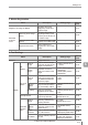

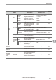
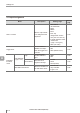


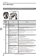

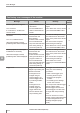
Table Of Contents
- Introduction
- Safety Information for IV Series
- Important Instructions
- Precautions on Regulations and Standards
- Version of the IV Series
- Structure of This Manual
- Contents
- Chapter 1 Getting Started
- Chapter 2 Installation and Connection
- Mounting the Sensor
- Mounting the Monitor
- Cables
- Chapter 3 Basic Operation
- Overview of Screen and Operation
- Basic Operation Flow
- Operation when the Power is Turned on
- Setting to the Factory Default
- Basic Operation for the Monitor
- Chapter 4 Settings Navigator (Setting the Judgment Condition)
- Settings Navigator
- Basic Operation of the Settings Navigator
- 1. Image Optimization (Clearly Image a Target)
- 2. Master Registration (Registering an Image as a Reference for Judgment)
- 3. Tool Settings (Setting the Judgment Method for Targets)
- 4. Output Assignment (Setting Details of Outputting to Output Line)
- Display Method of Extended Functions Menus
- Chapter 5 Operating/Adjusting
- Starting an Operation
- Overview of the Operation Screen
- Names and Functions of the Operation Screen
- Adjusting Thresholds for Judgment
- Tool Auto Tuning (Automatically Adjusting the Judgment Condition)
- Operation flow for the Tool Auto Tuning
- Starting and finishing the Tool Auto Tuning
- Registering the OK/NG images to be used for the Tool Auto Tuning
- Confirming or deleting the images registered for the Tool Auto Tuning
- Tool Auto Tuning by the previous registration information
- Tool Auto Tuning by the registration information file
- Stabilizing the Judgment Process
- Stabilizing the judgment process by taking a clear image of the target
- Imaging the target widely
- Correcting the distorted images due to the installation
- Achieving adequate image brightness
- Achieving good focus
- Reducing the image blur
- Reducing the shininess of the glossy or metal surface
- Adjusting the color tint (for color type only)
- Reducing the effect of illumination variation
- Stabilizing by correcting the misaligned target position
- Stabilizing the position adjustment
- Stabilizing the Outline tool
- ■Basic adjustments
- ■If the outline cannot be detected when the target becomes out of position
- ■If the detection becomes unstable due to the effect of the unwanted outline other than the target
- ■If the target tilts and the outline cannot be detected
- ■If the match rate difference between the high and low-quality-targets is small
- ■If the outline of the target cannot be detected
- Stabilizing the Color Area/Area tool
- Stabilizing the judgment process by taking a clear image of the target
- Shortening the Processing Time
- Chapter 6 Useful Features/Various Functions
- List of the Useful Features
- Displaying the Sensor Setup Menu Screen
- Changeover for a Target (Program Functions)
- Sensor Image History (Confirming the Images whose Status Result is NG)
- Saving the Sensor Settings and Images to a USB Memory
- Setting the Extended Functions of the Sensor
- Setting the Advanced Monitor Information
- Chapter 7 Controlling with Input/Output Line
- Chapter 8 Specifications
- Appendices
- Status Table
- Matching Rate of the Outline Tool and Position Adjustment Tool
- Settings List
- Troubleshooting
- Error Messages
- Remedy when the Monitor cannot be Connected with the Sensor
- Initializing the Network Settings (IP Reset Switch)
- Maintenance
- Index

A-21
- IV Series User's Manual (Monitor) -
A
Troubleshooting
Symptom Check point Remedy
Reference
page
An external trigger cannot
be input.
Is the trigger condition set to
[External]?
Select [External] in Trigger
Options.
4-8
Is the input line correctly
connected?
Correctly connect to the
external devices.
2-12
Has the input setting been
made correctly?
Make the input line and input
settings correctly in [Input
Settings].
6-26
Has the Polarity been correctly
set?
When the NPN is selected
in the Polarity, the circuit
becomes a non-voltage input
circuit. When the PNP is
selected in the Polarity, the
circuit becomes a voltage input
circuit. Check the cables.
6-28
The program number cannot
be changed with the input
line.
Has the switching method for
the programs been correctly
set?
Set the switching method for
the programs to [External IN]. 6-42
Has the input line been
correctly connected?
Correctly connect to the
external devices.
2-12
Has the input setting been
correctly set?
Set the input line and input
settings correctly in [Input
Settings].
6-26
Has the Polarity been correctly
set?
When the NPN is selected
in the Polarity, the circuit
becomes a non-voltage input
circuit. When the PNP is
selected in the Polarity, the
circuit becomes a voltage input
circuit. Check the cables.
6-28
The monitor and sensor
cannot be connected to.
Check the cables and settings.
Refer to “Remedy when the
Monitor cannot be Connected
with the Sensor” (Page A-28).
A-28
Image data cannot be
transferred via FTP.
Check the cables and settings.
Refer to “Remedy when data
transfer via FTP is unavailable”
A-38