
User guide
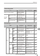

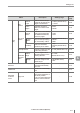
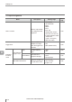


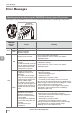

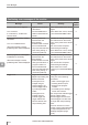
Table Of Contents
- Introduction
- Safety Information for IV Series
- Important Instructions
- Precautions on Regulations and Standards
- Version of the IV Series
- Structure of This Manual
- Contents
- Chapter 1 Getting Started
- Chapter 2 Installation and Connection
- Mounting the Sensor
- Mounting the Monitor
- Cables
- Chapter 3 Basic Operation
- Overview of Screen and Operation
- Basic Operation Flow
- Operation when the Power is Turned on
- Setting to the Factory Default
- Basic Operation for the Monitor
- Chapter 4 Settings Navigator (Setting the Judgment Condition)
- Settings Navigator
- Basic Operation of the Settings Navigator
- 1. Image Optimization (Clearly Image a Target)
- 2. Master Registration (Registering an Image as a Reference for Judgment)
- 3. Tool Settings (Setting the Judgment Method for Targets)
- 4. Output Assignment (Setting Details of Outputting to Output Line)
- Display Method of Extended Functions Menus
- Chapter 5 Operating/Adjusting
- Starting an Operation
- Overview of the Operation Screen
- Names and Functions of the Operation Screen
- Adjusting Thresholds for Judgment
- Tool Auto Tuning (Automatically Adjusting the Judgment Condition)
- Operation flow for the Tool Auto Tuning
- Starting and finishing the Tool Auto Tuning
- Registering the OK/NG images to be used for the Tool Auto Tuning
- Confirming or deleting the images registered for the Tool Auto Tuning
- Tool Auto Tuning by the previous registration information
- Tool Auto Tuning by the registration information file
- Stabilizing the Judgment Process
- Stabilizing the judgment process by taking a clear image of the target
- Imaging the target widely
- Correcting the distorted images due to the installation
- Achieving adequate image brightness
- Achieving good focus
- Reducing the image blur
- Reducing the shininess of the glossy or metal surface
- Adjusting the color tint (for color type only)
- Reducing the effect of illumination variation
- Stabilizing by correcting the misaligned target position
- Stabilizing the position adjustment
- Stabilizing the Outline tool
- ■Basic adjustments
- ■If the outline cannot be detected when the target becomes out of position
- ■If the detection becomes unstable due to the effect of the unwanted outline other than the target
- ■If the target tilts and the outline cannot be detected
- ■If the match rate difference between the high and low-quality-targets is small
- ■If the outline of the target cannot be detected
- Stabilizing the Color Area/Area tool
- Stabilizing the judgment process by taking a clear image of the target
- Shortening the Processing Time
- Chapter 6 Useful Features/Various Functions
- List of the Useful Features
- Displaying the Sensor Setup Menu Screen
- Changeover for a Target (Program Functions)
- Sensor Image History (Confirming the Images whose Status Result is NG)
- Saving the Sensor Settings and Images to a USB Memory
- Setting the Extended Functions of the Sensor
- Setting the Advanced Monitor Information
- Chapter 7 Controlling with Input/Output Line
- Chapter 8 Specifications
- Appendices
- Status Table
- Matching Rate of the Outline Tool and Position Adjustment Tool
- Settings List
- Troubleshooting
- Error Messages
- Remedy when the Monitor cannot be Connected with the Sensor
- Initializing the Network Settings (IP Reset Switch)
- Maintenance
- Index

A-19
- IV Series User's Manual (Monitor) -
A
Troubleshooting
Symptom Check point Remedy
Reference
page
The PWR/ERR indicator light
of the sensor or the PWR
indicator light of the monitor
is lighting or blinking in red.
An error occurred. Check the
errors from lighting or blinking
in red.
Refer to "Error Message".
A-22
An error message is
displayed on the monitor.
Check the details of the error
message.
Refer to "Error Message".
A-22
The power is not supplied to
the sensor or monitor does
not turn on.
Is the power cable correctly
connected?
Connect the power cable
correctly.
2-12
Is the voltage or capacity of
the power source meet the
specication?
Use a power source of the
correct rating.
8-2
An image is not displayed on
the monitor, or the image is
abnormal.
Is the installed distance of the
target correct?
Place a target at the correct
installed distance. The
installed distance depends on
the sensor type.
2-2
Is the sensor view correct?
Place the sensor in such a way
that the sensor view matches
the target size.
2-2
Is the focus adjustment correct?
Adjust the focusing position
(focus) of the sensor.
4-12
Is the brightness adjustment
correct?
Adjust the brightness of the
sensor.
4-11
Is the target or the sensor
vibrating?
Devise anti-vibration measures
etc.
-
Does the ambient light affect
the image?
Use brightness correction. 4-26
Place the douser to prevent
the incident of ambient light.
-
Is the front cover dirty or
damaged?
Clean the front cover. Replace
it with the spare front cover
(OP-87461).
A-41
Is the function of Update Image
in the RUN mode set to [OFF]?
Set the function of Update
Image in the RUN mode to [ON].
6-49
The image or the status
result is not updated.
Is the system in the setting
mode?
Start the run mode
Turn on the power of the
sensor again.
5-2
Is the trigger correctly input?
If a target is to be imaged
using an external trigger, input
the external trigger. When the
NPN is selected in the Polarity,
the circuit becomes a non-
voltage input circuit. When
PNP is selected in the Polarity,
the circuit becomes a voltage
input circuit. Check the cables.
2-12
All or part of the settings
necessary for running have not
been completed.
Complete the settings in
Settings Navigator. 4-1
Troubleshooting