
User guide
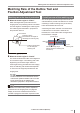
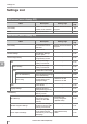
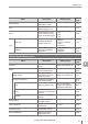

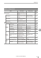


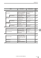
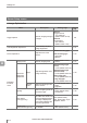
Table Of Contents
- Introduction
- Safety Information for IV Series
- Important Instructions
- Precautions on Regulations and Standards
- Version of the IV Series
- Structure of This Manual
- Contents
- Chapter 1 Getting Started
- Chapter 2 Installation and Connection
- Mounting the Sensor
- Mounting the Monitor
- Cables
- Chapter 3 Basic Operation
- Overview of Screen and Operation
- Basic Operation Flow
- Operation when the Power is Turned on
- Setting to the Factory Default
- Basic Operation for the Monitor
- Chapter 4 Settings Navigator (Setting the Judgment Condition)
- Settings Navigator
- Basic Operation of the Settings Navigator
- 1. Image Optimization (Clearly Image a Target)
- 2. Master Registration (Registering an Image as a Reference for Judgment)
- 3. Tool Settings (Setting the Judgment Method for Targets)
- 4. Output Assignment (Setting Details of Outputting to Output Line)
- Display Method of Extended Functions Menus
- Chapter 5 Operating/Adjusting
- Starting an Operation
- Overview of the Operation Screen
- Names and Functions of the Operation Screen
- Adjusting Thresholds for Judgment
- Tool Auto Tuning (Automatically Adjusting the Judgment Condition)
- Operation flow for the Tool Auto Tuning
- Starting and finishing the Tool Auto Tuning
- Registering the OK/NG images to be used for the Tool Auto Tuning
- Confirming or deleting the images registered for the Tool Auto Tuning
- Tool Auto Tuning by the previous registration information
- Tool Auto Tuning by the registration information file
- Stabilizing the Judgment Process
- Stabilizing the judgment process by taking a clear image of the target
- Imaging the target widely
- Correcting the distorted images due to the installation
- Achieving adequate image brightness
- Achieving good focus
- Reducing the image blur
- Reducing the shininess of the glossy or metal surface
- Adjusting the color tint (for color type only)
- Reducing the effect of illumination variation
- Stabilizing by correcting the misaligned target position
- Stabilizing the position adjustment
- Stabilizing the Outline tool
- ■Basic adjustments
- ■If the outline cannot be detected when the target becomes out of position
- ■If the detection becomes unstable due to the effect of the unwanted outline other than the target
- ■If the target tilts and the outline cannot be detected
- ■If the match rate difference between the high and low-quality-targets is small
- ■If the outline of the target cannot be detected
- Stabilizing the Color Area/Area tool
- Stabilizing the judgment process by taking a clear image of the target
- Shortening the Processing Time
- Chapter 6 Useful Features/Various Functions
- List of the Useful Features
- Displaying the Sensor Setup Menu Screen
- Changeover for a Target (Program Functions)
- Sensor Image History (Confirming the Images whose Status Result is NG)
- Saving the Sensor Settings and Images to a USB Memory
- Setting the Extended Functions of the Sensor
- Setting the Advanced Monitor Information
- Chapter 7 Controlling with Input/Output Line
- Chapter 8 Specifications
- Appendices
- Status Table
- Matching Rate of the Outline Tool and Position Adjustment Tool
- Settings List
- Troubleshooting
- Error Messages
- Remedy when the Monitor cannot be Connected with the Sensor
- Initializing the Network Settings (IP Reset Switch)
- Maintenance
- Index

A-11
- IV Series User's Manual (Monitor) -
A
Settings List
Sensor Advanced screen
Menu Description Setting range
Reference
page
Environmental 6-25
I/O Settings
Input
Settings
IN1
Sets a detection timing of
the trigger input for IN1
input line.
Ext. Trigger ↑
Ext. Trigger ↓
6-26
IN2 to IN6
Sets a function to the
input line IN2 to IN6.
OFF
Program bit0 to bit4
Clear Error
Ext. Master Save
6-26
Option
Sets whether or not to
write data into ROM
when the external master
image registration is
performed.
Yes
No (default value)
6-26
Output
Settings
OUT1 to
OUT4
Sets the output line
settings (OUT1 to 4).
N.O.
N.C.
6-27
Common
Output
Settings
Selects an output mode.
Latching (default value)
One-Shot
6-27
Polarity
Selects the polarity (I/O
format) of the sensor.
NPN
PNP
6-28
I/O Monitor
Checks whether an input
line for control is correctly
wired or not.
ON
OFF
6-28
Device
Name/
Pass
Device Name
Sets a name of the sensor.
Up to 16 characters
(English and Japanese
single byte characters)
6-29
Security
Password
Lock
Sets the Password
Lock function to enable/
disable.
ON
OFF (default value)
6-30
Password
Sets a password when the
Password Lock function of
the sensor is enabled.
Up to 8 characters
(English and Japanese
single byte characters)
6-30
Network
Settings
MAC Address
Displays the MAC
address for the sensor.
- 6-31
IP Address
Displays the IP address
of the sensor.
- 6-31
Subnet Mask
Displays the subnet mask
of the sensor.
- 6-31
Default Gateway
Displays the default
gateway of the sensor.
- 6-31