
User guide


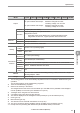


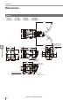

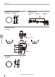
Table Of Contents
- Introduction
- Safety Information for IV Series
- Important Instructions
- Precautions on Regulations and Standards
- Version of the IV Series
- Structure of This Manual
- Contents
- Chapter 1 Getting Started
- Chapter 2 Installation and Connection
- Mounting the Sensor
- Mounting the Monitor
- Cables
- Chapter 3 Basic Operation
- Overview of Screen and Operation
- Basic Operation Flow
- Operation when the Power is Turned on
- Setting to the Factory Default
- Basic Operation for the Monitor
- Chapter 4 Settings Navigator (Setting the Judgment Condition)
- Settings Navigator
- Basic Operation of the Settings Navigator
- 1. Image Optimization (Clearly Image a Target)
- 2. Master Registration (Registering an Image as a Reference for Judgment)
- 3. Tool Settings (Setting the Judgment Method for Targets)
- 4. Output Assignment (Setting Details of Outputting to Output Line)
- Display Method of Extended Functions Menus
- Chapter 5 Operating/Adjusting
- Starting an Operation
- Overview of the Operation Screen
- Names and Functions of the Operation Screen
- Adjusting Thresholds for Judgment
- Tool Auto Tuning (Automatically Adjusting the Judgment Condition)
- Operation flow for the Tool Auto Tuning
- Starting and finishing the Tool Auto Tuning
- Registering the OK/NG images to be used for the Tool Auto Tuning
- Confirming or deleting the images registered for the Tool Auto Tuning
- Tool Auto Tuning by the previous registration information
- Tool Auto Tuning by the registration information file
- Stabilizing the Judgment Process
- Stabilizing the judgment process by taking a clear image of the target
- Imaging the target widely
- Correcting the distorted images due to the installation
- Achieving adequate image brightness
- Achieving good focus
- Reducing the image blur
- Reducing the shininess of the glossy or metal surface
- Adjusting the color tint (for color type only)
- Reducing the effect of illumination variation
- Stabilizing by correcting the misaligned target position
- Stabilizing the position adjustment
- Stabilizing the Outline tool
- ■Basic adjustments
- ■If the outline cannot be detected when the target becomes out of position
- ■If the detection becomes unstable due to the effect of the unwanted outline other than the target
- ■If the target tilts and the outline cannot be detected
- ■If the match rate difference between the high and low-quality-targets is small
- ■If the outline of the target cannot be detected
- Stabilizing the Color Area/Area tool
- Stabilizing the judgment process by taking a clear image of the target
- Shortening the Processing Time
- Chapter 6 Useful Features/Various Functions
- List of the Useful Features
- Displaying the Sensor Setup Menu Screen
- Changeover for a Target (Program Functions)
- Sensor Image History (Confirming the Images whose Status Result is NG)
- Saving the Sensor Settings and Images to a USB Memory
- Setting the Extended Functions of the Sensor
- Setting the Advanced Monitor Information
- Chapter 7 Controlling with Input/Output Line
- Chapter 8 Specifications
- Appendices
- Status Table
- Matching Rate of the Outline Tool and Position Adjustment Tool
- Settings List
- Troubleshooting
- Error Messages
- Remedy when the Monitor cannot be Connected with the Sensor
- Initializing the Network Settings (IP Reset Switch)
- Maintenance
- Index

8-2
- IV Series User's Manual (Monitor) -
Specications
Sensor
Model IV-500C
IV-500CA
IV-500M
IV-500MA
IV-150M
IV-150MA IV-2000M
IV-2000MA
Installed distance
Standard range Short range Long range
50 to 500mm 50 to 150mm
300 to 2000mm
View
Installed distance 50 mm :
25 (H) x 18 (V) mm
to
Installed distance 500mm :
210 (H) x 157 (V) mm
Installed distance
50mm :
12 (H) x 9 (V) mm
to
Installed distance
150mm :
36 (H) x 27 (V) mm
Installed distance
300mm :
45 (H) x 33 (V) mm
to
Installed distance
2000mm :
300 (H) x 225 (V) mm
Image sensor
1/3 inch
color CMOS
1/3 inch
monochrome CMOS
Pixel 752 (H) x 480 (V)
Focus adjustment Manual Auto
*1
Manual Auto
*1
Manual Auto
*1
Manual Auto
*1
Exposure time 1/10 to 1/50,000 1/10 to 1/25,000 1/20 to 1/25,000 1/10 to 1/25,000
Light
Amplier type
White LED Red LED Infrared LED
Lighting
method
Pulse lighting/DC lighting is switchable
Tool
Type Outline search, Color area
*7
, Area
*8
, Position adjustment
Number
*2
Detection tools : 16 tools, Position adjustment tool : 1 tool
Switch settings
(programs)
32 programs
Image
history
*3
Numbers 100 images
*4
300 images
*5
Condition NG only/All is selectable
Analysis information
*6
OFF/Statistics/Histograms is switchable
Statistics : Processing time (latest value, MAX, MIN, AVE), numbers of OKs,
numbers of NGs, trigger numbers, trigger errors,
judge results list by tools
Histograms : Histogram, matching degree (latest value, MAX, MIN, AVE),
numbers of OKs, numbers of NGs
Other functions
HDR, HighGain, Color lters
*7
, Digital zoom
*8
, Brightness correction,
Tilt correction, White balance
*7
, Mask outline, Mask area, Test run,
ToolAutoTune, Input monitor, Output test, Security settings, Simulator
*9
Indicators PWR/ERR, OUT, TRIG, STATUS, LINK/ACT
Input
No-voltage input/voltage input is switchable
For no-voltage input :
ON voltage 2V or lower, OFF current 0.1mA or lower, ON
current 2mA (short circuit)
For voltage input : Maximum input rating 26.4V, ON voltage 15V or higher,
OFF current 0.2mA or lower, ON current 2mA (for 24V)
Inputs 6 inputs (IN1 to IN6)
Function
IN1 : External trigger, IN2 to IN6 : Enable by assigning the optional functions
Assignable functions :
Program switching, Clear error, External master image registration
Specications
8
Specications