
User guide


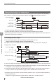


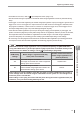

Table Of Contents
- Introduction
- Safety Information for IV Series
- Important Instructions
- Precautions on Regulations and Standards
- Version of the IV Series
- Structure of This Manual
- Contents
- Chapter 1 Getting Started
- Chapter 2 Installation and Connection
- Mounting the Sensor
- Mounting the Monitor
- Cables
- Chapter 3 Basic Operation
- Overview of Screen and Operation
- Basic Operation Flow
- Operation when the Power is Turned on
- Setting to the Factory Default
- Basic Operation for the Monitor
- Chapter 4 Settings Navigator (Setting the Judgment Condition)
- Settings Navigator
- Basic Operation of the Settings Navigator
- 1. Image Optimization (Clearly Image a Target)
- 2. Master Registration (Registering an Image as a Reference for Judgment)
- 3. Tool Settings (Setting the Judgment Method for Targets)
- 4. Output Assignment (Setting Details of Outputting to Output Line)
- Display Method of Extended Functions Menus
- Chapter 5 Operating/Adjusting
- Starting an Operation
- Overview of the Operation Screen
- Names and Functions of the Operation Screen
- Adjusting Thresholds for Judgment
- Tool Auto Tuning (Automatically Adjusting the Judgment Condition)
- Operation flow for the Tool Auto Tuning
- Starting and finishing the Tool Auto Tuning
- Registering the OK/NG images to be used for the Tool Auto Tuning
- Confirming or deleting the images registered for the Tool Auto Tuning
- Tool Auto Tuning by the previous registration information
- Tool Auto Tuning by the registration information file
- Stabilizing the Judgment Process
- Stabilizing the judgment process by taking a clear image of the target
- Imaging the target widely
- Correcting the distorted images due to the installation
- Achieving adequate image brightness
- Achieving good focus
- Reducing the image blur
- Reducing the shininess of the glossy or metal surface
- Adjusting the color tint (for color type only)
- Reducing the effect of illumination variation
- Stabilizing by correcting the misaligned target position
- Stabilizing the position adjustment
- Stabilizing the Outline tool
- ■Basic adjustments
- ■If the outline cannot be detected when the target becomes out of position
- ■If the detection becomes unstable due to the effect of the unwanted outline other than the target
- ■If the target tilts and the outline cannot be detected
- ■If the match rate difference between the high and low-quality-targets is small
- ■If the outline of the target cannot be detected
- Stabilizing the Color Area/Area tool
- Stabilizing the judgment process by taking a clear image of the target
- Shortening the Processing Time
- Chapter 6 Useful Features/Various Functions
- List of the Useful Features
- Displaying the Sensor Setup Menu Screen
- Changeover for a Target (Program Functions)
- Sensor Image History (Confirming the Images whose Status Result is NG)
- Saving the Sensor Settings and Images to a USB Memory
- Setting the Extended Functions of the Sensor
- Setting the Advanced Monitor Information
- Chapter 7 Controlling with Input/Output Line
- Chapter 8 Specifications
- Appendices
- Status Table
- Matching Rate of the Outline Tool and Position Adjustment Tool
- Settings List
- Troubleshooting
- Error Messages
- Remedy when the Monitor cannot be Connected with the Sensor
- Initializing the Network Settings (IP Reset Switch)
- Maintenance
- Index

7-9
- IV Series User's Manual (Monitor) -
Registering the Master Image
For details of T3 and T4, refer to “Input Response Time” (Page 7-12).
Use this function during an operation. The external master image registration cannot be performed during
setup.
If the trigger occurs while registering the master image (during BUSY output), the trigger is ignored and a
trigger error occurs. The trigger error output function turns OFF when the next trigger is activated, when
the program is switched, or when the error is cleared. To output the trigger error, set the trigger error in
the Output Assignment (Page 4-60) under Settings Navigator to [ON].
If the external master registration input is input during the imaging process (BUSY) by the trigger, the
system cancels the judgment process (taken image will not be registered). After the process is canceled,
the image taken before cancellation is registered as a master image. The master image registration
process is delayed by the cancelling process. Delaying time differs depending on the settings.
Do not change over the programs at the same time as external master registration input is being performed.
The sequence of the external master registration and switching programs process will vary.
If the external master image registration is to be performed frequently, set [Write ROM when
using “Ext. Master Save”?] of the input option to [No] to protect the nonvolatile memory of the
internal sensor. For details of settings, refer to “Input Settings” (Page 6-26).
ROM writing
settings
Master image is registered externally
when power is turned OFF
Number of times that external
master image registration can
perform (duration)
Yes
The master image is not deleted.
The image can be used as a master image after
starting up the device next time.
100,000 times
No
The master image is deleted.
External master image registration needs to be
performed after starting up the device.
No limit
If the setting for writing to ROM is set to [No], the image is written to ROM when the system is
in the settings mode. The master image is not deleted once the system is in the settings mode
before the power is turned OFF.
If the setting is set to [Yes], do not turn OFF the power during the master registration time (T3).
Otherwise, all or part of the setting data may be lost.
7
Controlling with the Input/Output Line