
User guide


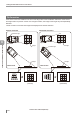
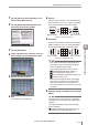


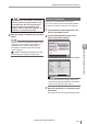
Table Of Contents
- Introduction
- Safety Information for IV Series
- Important Instructions
- Precautions on Regulations and Standards
- Version of the IV Series
- Structure of This Manual
- Contents
- Chapter 1 Getting Started
- Chapter 2 Installation and Connection
- Mounting the Sensor
- Mounting the Monitor
- Cables
- Chapter 3 Basic Operation
- Overview of Screen and Operation
- Basic Operation Flow
- Operation when the Power is Turned on
- Setting to the Factory Default
- Basic Operation for the Monitor
- Chapter 4 Settings Navigator (Setting the Judgment Condition)
- Settings Navigator
- Basic Operation of the Settings Navigator
- 1. Image Optimization (Clearly Image a Target)
- 2. Master Registration (Registering an Image as a Reference for Judgment)
- 3. Tool Settings (Setting the Judgment Method for Targets)
- 4. Output Assignment (Setting Details of Outputting to Output Line)
- Display Method of Extended Functions Menus
- Chapter 5 Operating/Adjusting
- Starting an Operation
- Overview of the Operation Screen
- Names and Functions of the Operation Screen
- Adjusting Thresholds for Judgment
- Tool Auto Tuning (Automatically Adjusting the Judgment Condition)
- Operation flow for the Tool Auto Tuning
- Starting and finishing the Tool Auto Tuning
- Registering the OK/NG images to be used for the Tool Auto Tuning
- Confirming or deleting the images registered for the Tool Auto Tuning
- Tool Auto Tuning by the previous registration information
- Tool Auto Tuning by the registration information file
- Stabilizing the Judgment Process
- Stabilizing the judgment process by taking a clear image of the target
- Imaging the target widely
- Correcting the distorted images due to the installation
- Achieving adequate image brightness
- Achieving good focus
- Reducing the image blur
- Reducing the shininess of the glossy or metal surface
- Adjusting the color tint (for color type only)
- Reducing the effect of illumination variation
- Stabilizing by correcting the misaligned target position
- Stabilizing the position adjustment
- Stabilizing the Outline tool
- ■Basic adjustments
- ■If the outline cannot be detected when the target becomes out of position
- ■If the detection becomes unstable due to the effect of the unwanted outline other than the target
- ■If the target tilts and the outline cannot be detected
- ■If the match rate difference between the high and low-quality-targets is small
- ■If the outline of the target cannot be detected
- Stabilizing the Color Area/Area tool
- Stabilizing the judgment process by taking a clear image of the target
- Shortening the Processing Time
- Chapter 6 Useful Features/Various Functions
- List of the Useful Features
- Displaying the Sensor Setup Menu Screen
- Changeover for a Target (Program Functions)
- Sensor Image History (Confirming the Images whose Status Result is NG)
- Saving the Sensor Settings and Images to a USB Memory
- Setting the Extended Functions of the Sensor
- Setting the Advanced Monitor Information
- Chapter 7 Controlling with Input/Output Line
- Chapter 8 Specifications
- Appendices
- Status Table
- Matching Rate of the Outline Tool and Position Adjustment Tool
- Settings List
- Troubleshooting
- Error Messages
- Remedy when the Monitor cannot be Connected with the Sensor
- Initializing the Network Settings (IP Reset Switch)
- Maintenance
- Index
6-35
- IV Series User's Manual (Monitor) -
Setting the Extended Functions of the Sensor
File Format
Selects the le saving format for image data.
IVP
Transfers the image data as the format which
can be opened by IV-Navigator. Operation
results can be conrmed in the simulator
function by using the transferred image data.
Moreover, the image data can be converted to
the BMP format by using the IVP-Converter.
BMP
Transfers the image data as the format which
can be opened by other applications.
Transfer Judgment Results
To transfer judgement results simultaneously
with the image data, select [Enable].
Judgement results are transferred as a tab
delimited text.
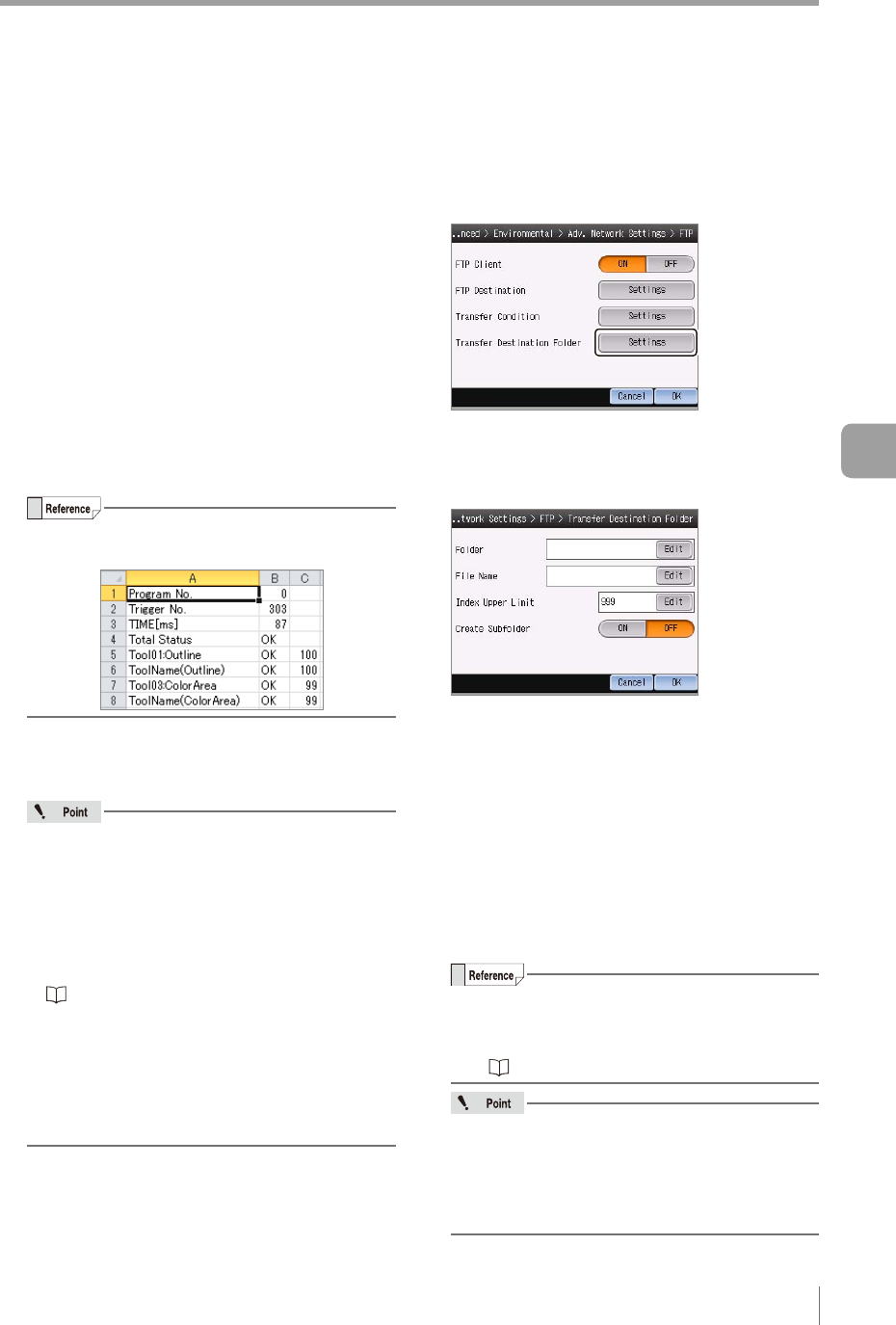
The example for displaying the saved results
le with Microsoft Excel is as follows.
FTP Error
To turn ON the error output function for when a
le transfer failed, select [Enable].
When this item is set to [Enable], the
followings occur if a le transfer fails.
The following error messages are displayed
in response to the causes of failure.
- FTP Connection Error
- FTP Transfer Error (Transfer Failed)
- FTP Transfer Error (Insufcient Data Buffer)
“Remedy when data transfer via FTP is
unavailable” (Page A-38)
The error output function turns ON.
The indicator light of the sensor blinks in red.
If “FTP Transfer Error” has occurred while
the sensor is running, the error condition will
continue until the error is cleared.
3
After the setting is completed, tap the [OK]
button.
The system returns to the main screen of the
FTP Settings.
Transfer Destination Folder Settings
1
Tap the [Settings] button in the “Transfer
Destination Folder”.
The Transfer Destination Folder screen opens.
2
Specify the transfer destination folder of
FTP server.
Folder
Species the transfer destination folder of FTP server.
Set an arbitrary folder name.
Input is not necessary if the image data is to
be transferred to the root folder.
To specify a subfolder, break it with “/” (one-
byte slash).
If the specied folder does not exist, a new
folder will be created.
When the [Edit] button is tapped, the “Folder”
screen opens.
Set an arbitrary folder name and tap the [OK] button.
Default: None (blank). Up to 16 characters
can be set.
For details of how to enter characters, refer
to “Inputting characters” (Page 3-16).
“/” (one-byte slash), “.” (one-byte point) and
“ ” (one-byte space) cannot be used as the
rst nor last letter of the folder name.
“/” (one-byte slash) cannot be used multiple
times in a row.
6
Useful Features/Various Functions