
User guide
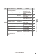
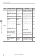


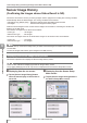
Table Of Contents
- Introduction
- Safety Information for IV Series
- Important Instructions
- Precautions on Regulations and Standards
- Version of the IV Series
- Structure of This Manual
- Contents
- Chapter 1 Getting Started
- Chapter 2 Installation and Connection
- Mounting the Sensor
- Mounting the Monitor
- Cables
- Chapter 3 Basic Operation
- Overview of Screen and Operation
- Basic Operation Flow
- Operation when the Power is Turned on
- Setting to the Factory Default
- Basic Operation for the Monitor
- Chapter 4 Settings Navigator (Setting the Judgment Condition)
- Settings Navigator
- Basic Operation of the Settings Navigator
- 1. Image Optimization (Clearly Image a Target)
- 2. Master Registration (Registering an Image as a Reference for Judgment)
- 3. Tool Settings (Setting the Judgment Method for Targets)
- 4. Output Assignment (Setting Details of Outputting to Output Line)
- Display Method of Extended Functions Menus
- Chapter 5 Operating/Adjusting
- Starting an Operation
- Overview of the Operation Screen
- Names and Functions of the Operation Screen
- Adjusting Thresholds for Judgment
- Tool Auto Tuning (Automatically Adjusting the Judgment Condition)
- Operation flow for the Tool Auto Tuning
- Starting and finishing the Tool Auto Tuning
- Registering the OK/NG images to be used for the Tool Auto Tuning
- Confirming or deleting the images registered for the Tool Auto Tuning
- Tool Auto Tuning by the previous registration information
- Tool Auto Tuning by the registration information file
- Stabilizing the Judgment Process
- Stabilizing the judgment process by taking a clear image of the target
- Imaging the target widely
- Correcting the distorted images due to the installation
- Achieving adequate image brightness
- Achieving good focus
- Reducing the image blur
- Reducing the shininess of the glossy or metal surface
- Adjusting the color tint (for color type only)
- Reducing the effect of illumination variation
- Stabilizing by correcting the misaligned target position
- Stabilizing the position adjustment
- Stabilizing the Outline tool
- ■Basic adjustments
- ■If the outline cannot be detected when the target becomes out of position
- ■If the detection becomes unstable due to the effect of the unwanted outline other than the target
- ■If the target tilts and the outline cannot be detected
- ■If the match rate difference between the high and low-quality-targets is small
- ■If the outline of the target cannot be detected
- Stabilizing the Color Area/Area tool
- Stabilizing the judgment process by taking a clear image of the target
- Shortening the Processing Time
- Chapter 6 Useful Features/Various Functions
- List of the Useful Features
- Displaying the Sensor Setup Menu Screen
- Changeover for a Target (Program Functions)
- Sensor Image History (Confirming the Images whose Status Result is NG)
- Saving the Sensor Settings and Images to a USB Memory
- Setting the Extended Functions of the Sensor
- Setting the Advanced Monitor Information
- Chapter 7 Controlling with Input/Output Line
- Chapter 8 Specifications
- Appendices
- Status Table
- Matching Rate of the Outline Tool and Position Adjustment Tool
- Settings List
- Troubleshooting
- Error Messages
- Remedy when the Monitor cannot be Connected with the Sensor
- Initializing the Network Settings (IP Reset Switch)
- Maintenance
- Index

6-6
- IV Series User's Manual (Monitor) -
List of the Useful Features
Items Things you want to do Useful functions Description
Reference
page
I/O lines
Conrm whether or not the
input and output lines are
correctly wired
I/O Monitor
The operation test for the input
and output line can be performed.
6-28
Switch to NPN output or PNP
output
Polarity
The polarity can be changed
to NPN or PNP according to
the controlling device used.
6-28
Switch the output to N.O. or N.C.
Output Settings
The settings for each OUT can
be changed to N.O. or N.C.
6-27
Output the status output with
one-shot
Common Output
Settings
The output can be changed
from latching output to one-
shot output.
6-27
Output the status output with
on-delay
Common Output
Settings
On-delay time can be set for
the one-shot output.
6-27
Switch the external trigger to
rise or fall
Input Settings
Rising trigger or falling
trigger can be selected as
the operation of the external
trigger
6-26
Output the NG status results
Total status NG
output
When the total status result
of each detection tool was
NG, the total status NG output
function turns ON.
4-60
Conrm whether or not the
sensor is running properly
RUN output
When the sensor is running
with no system error occurring,
the output function turns ON.
4-60
Form a logical operation of
status result
Logic output
Logical operation result of each
detection tool can be assigned
to the output function.
4-63
Change the total status
conditions
Total status
conditions
The total status conditions can
be selected from [All Tools OK]/
[Any Tool OK]/[Logic 1] to [Logic
4].
4-65
6
Useful Features/Various Functions