
User guide
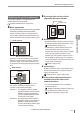
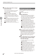
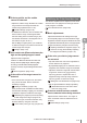

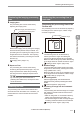


Table Of Contents
- Introduction
- Safety Information for IV Series
- Important Instructions
- Precautions on Regulations and Standards
- Version of the IV Series
- Structure of This Manual
- Contents
- Chapter 1 Getting Started
- Chapter 2 Installation and Connection
- Mounting the Sensor
- Mounting the Monitor
- Cables
- Chapter 3 Basic Operation
- Overview of Screen and Operation
- Basic Operation Flow
- Operation when the Power is Turned on
- Setting to the Factory Default
- Basic Operation for the Monitor
- Chapter 4 Settings Navigator (Setting the Judgment Condition)
- Settings Navigator
- Basic Operation of the Settings Navigator
- 1. Image Optimization (Clearly Image a Target)
- 2. Master Registration (Registering an Image as a Reference for Judgment)
- 3. Tool Settings (Setting the Judgment Method for Targets)
- 4. Output Assignment (Setting Details of Outputting to Output Line)
- Display Method of Extended Functions Menus
- Chapter 5 Operating/Adjusting
- Starting an Operation
- Overview of the Operation Screen
- Names and Functions of the Operation Screen
- Adjusting Thresholds for Judgment
- Tool Auto Tuning (Automatically Adjusting the Judgment Condition)
- Operation flow for the Tool Auto Tuning
- Starting and finishing the Tool Auto Tuning
- Registering the OK/NG images to be used for the Tool Auto Tuning
- Confirming or deleting the images registered for the Tool Auto Tuning
- Tool Auto Tuning by the previous registration information
- Tool Auto Tuning by the registration information file
- Stabilizing the Judgment Process
- Stabilizing the judgment process by taking a clear image of the target
- Imaging the target widely
- Correcting the distorted images due to the installation
- Achieving adequate image brightness
- Achieving good focus
- Reducing the image blur
- Reducing the shininess of the glossy or metal surface
- Adjusting the color tint (for color type only)
- Reducing the effect of illumination variation
- Stabilizing by correcting the misaligned target position
- Stabilizing the position adjustment
- Stabilizing the Outline tool
- ■Basic adjustments
- ■If the outline cannot be detected when the target becomes out of position
- ■If the detection becomes unstable due to the effect of the unwanted outline other than the target
- ■If the target tilts and the outline cannot be detected
- ■If the match rate difference between the high and low-quality-targets is small
- ■If the outline of the target cannot be detected
- Stabilizing the Color Area/Area tool
- Stabilizing the judgment process by taking a clear image of the target
- Shortening the Processing Time
- Chapter 6 Useful Features/Various Functions
- List of the Useful Features
- Displaying the Sensor Setup Menu Screen
- Changeover for a Target (Program Functions)
- Sensor Image History (Confirming the Images whose Status Result is NG)
- Saving the Sensor Settings and Images to a USB Memory
- Setting the Extended Functions of the Sensor
- Setting the Advanced Monitor Information
- Chapter 7 Controlling with Input/Output Line
- Chapter 8 Specifications
- Appendices
- Status Table
- Matching Rate of the Outline Tool and Position Adjustment Tool
- Settings List
- Troubleshooting
- Error Messages
- Remedy when the Monitor cannot be Connected with the Sensor
- Initializing the Network Settings (IP Reset Switch)
- Maintenance
- Index

5-37
- IV Series User's Manual (Monitor) -
Stabilizing the Judgment Process
Stabilizing the position adjustment
This section explains how to adjust when the
position adjustment is not stable.
“Position Adjustment tool” (Page 4-51)
Basic adjustments
Set the position adjustment window as large as possible
by selecting a part that contains a unique shape.
If there are many variation of a target shapes
that a position adjustment window has been set,
set the threshold which has lower matching rate.
: Good example
Position adjustment window
Since the convex part assigned in the position
adjustment window does not exist in any other
part of the target, the position adjustment can
be performed correctly without being recognition
error.
×
: Bad example
Position adjustment window
Example 1
Example 2
The position adjustment cannot function
correctly in the following examples.
Example 1: The straight line that the position
adjustment window is set cannot be
identied uniquely because there
are many similar straight lines exist
in other parts of the target.
Example 2:
The angle section that the position
adjustment window is set cannot be
identied
uniquely
because there
are many similar angle sections exist
in other parts of the target.
If the target tilts and the position
adjustment becomes unstable
Search region
Rotation range
Rotation Range
Broaden the rotation range if the tilt of the target
exceeds the rotation range (default value: ± 20°).
“Rotation Range” (Page 4-57)
To stabilize the position adjustment, the tool
window will search with the range ± few
degrees wider than the setting value of rotation
range. (The tool window will search ± few
degrees even if the rotation range is set to 0°.)
Set the Margin to [OFF] when you would like
to detect the target in accordance with the set
rotation angle of the target.
“Margin” (Page 4-57)
Search Region
Broaden the search region if the variation in the
position determining of the target exceeds the
region to be searched.
“Setting a search region” (Page 4-55)
If the position adjustment becomes
unstable due to the effect of the
unwanted outlines
The outline disabling function can disable
unwanted outlines.
“Settings for disabling outlines” (Page 4-55)
Set the extraction sensitivity to [Low].
“Setting a sensitivity” (Page 4-56)
5
Operating/Adjusting