
User guide
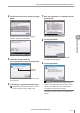


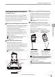

Table Of Contents
- Introduction
- Safety Information for IV Series
- Important Instructions
- Precautions on Regulations and Standards
- Version of the IV Series
- Structure of This Manual
- Contents
- Chapter 1 Getting Started
- Chapter 2 Installation and Connection
- Mounting the Sensor
- Mounting the Monitor
- Cables
- Chapter 3 Basic Operation
- Overview of Screen and Operation
- Basic Operation Flow
- Operation when the Power is Turned on
- Setting to the Factory Default
- Basic Operation for the Monitor
- Chapter 4 Settings Navigator (Setting the Judgment Condition)
- Settings Navigator
- Basic Operation of the Settings Navigator
- 1. Image Optimization (Clearly Image a Target)
- 2. Master Registration (Registering an Image as a Reference for Judgment)
- 3. Tool Settings (Setting the Judgment Method for Targets)
- 4. Output Assignment (Setting Details of Outputting to Output Line)
- Display Method of Extended Functions Menus
- Chapter 5 Operating/Adjusting
- Starting an Operation
- Overview of the Operation Screen
- Names and Functions of the Operation Screen
- Adjusting Thresholds for Judgment
- Tool Auto Tuning (Automatically Adjusting the Judgment Condition)
- Operation flow for the Tool Auto Tuning
- Starting and finishing the Tool Auto Tuning
- Registering the OK/NG images to be used for the Tool Auto Tuning
- Confirming or deleting the images registered for the Tool Auto Tuning
- Tool Auto Tuning by the previous registration information
- Tool Auto Tuning by the registration information file
- Stabilizing the Judgment Process
- Stabilizing the judgment process by taking a clear image of the target
- Imaging the target widely
- Correcting the distorted images due to the installation
- Achieving adequate image brightness
- Achieving good focus
- Reducing the image blur
- Reducing the shininess of the glossy or metal surface
- Adjusting the color tint (for color type only)
- Reducing the effect of illumination variation
- Stabilizing by correcting the misaligned target position
- Stabilizing the position adjustment
- Stabilizing the Outline tool
- ■Basic adjustments
- ■If the outline cannot be detected when the target becomes out of position
- ■If the detection becomes unstable due to the effect of the unwanted outline other than the target
- ■If the target tilts and the outline cannot be detected
- ■If the match rate difference between the high and low-quality-targets is small
- ■If the outline of the target cannot be detected
- Stabilizing the Color Area/Area tool
- Stabilizing the judgment process by taking a clear image of the target
- Shortening the Processing Time
- Chapter 6 Useful Features/Various Functions
- List of the Useful Features
- Displaying the Sensor Setup Menu Screen
- Changeover for a Target (Program Functions)
- Sensor Image History (Confirming the Images whose Status Result is NG)
- Saving the Sensor Settings and Images to a USB Memory
- Setting the Extended Functions of the Sensor
- Setting the Advanced Monitor Information
- Chapter 7 Controlling with Input/Output Line
- Chapter 8 Specifications
- Appendices
- Status Table
- Matching Rate of the Outline Tool and Position Adjustment Tool
- Settings List
- Troubleshooting
- Error Messages
- Remedy when the Monitor cannot be Connected with the Sensor
- Initializing the Network Settings (IP Reset Switch)
- Maintenance
- Index

5-35
- IV Series User's Manual (Monitor) -
Stabilizing the Judgment Process
Reducing the shininess of the glossy
or metal surface
Glossy and/or metal surface may reect the built-in
light into the camera. Since mirror reection has a
high-light intensity, the amount of light received will
be saturated and the surface will shine. This section
explains how to reduce the shininess.
Using the Auto Brightness Adjustment
If the target shines, the HDR function is enabled
automatically and it can be reduced by using
the auto brightness adjustment.
The HDR (High Dynamic Range) function is
a function that prevents light saturation in the
shining area by imaging the target with a wider
dynamic range. The HDR function can also be
adjusted manually.
“Auto Brightness Adjustment” (Page 4-11)
“Advanced Brightness Adjustment”
(Page 4-18)
Using the dome attachment
Use the dome attachment (IV-D10).
The dome attachment emits even diffused light
from the entire circumference to the target, so
that the contrast becomes less and the shine on
the target’s surface is reduced.
This is effective for targets of all shapes.
“Using the dome attachment” (Page 2-6)
Target
Diffusion
light
Dome attachment
Using the polarizing lter attachment
Use the polarizing lter attachment (OP-87436/
OP-87437). The optical characteristics of the
polarizing lter attachment cut off the mirror
reection and reduce the shine on the target’s
surface.
“Using the polarizing lter attachment”
(Page 2-7)
Installing the sensor at an angle
The built-in lighting will not reected back into
the camera, so the shine on the target’s surface
can be reduced.
This is effective for at-surface targets.
When the sensor is
installed in front of
the target
When the sensor is
installed at an angle
from the target
The mirror reection
of the built-in light
reects into the
camera and causes
the surface to shine.
The mirror reection
of the built-in light
does not reect into
the camera so no
surface shine occurs.
If the image is distorted by tilting the sensor,
the image can be corrected by the tilt
correction function.
“Tilt Correction” (Page 6-38)
5
Operating/Adjusting