
User guide

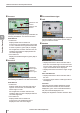


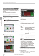
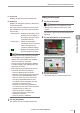
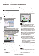
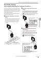
Table Of Contents
- Introduction
- Safety Information for IV Series
- Important Instructions
- Precautions on Regulations and Standards
- Version of the IV Series
- Structure of This Manual
- Contents
- Chapter 1 Getting Started
- Chapter 2 Installation and Connection
- Mounting the Sensor
- Mounting the Monitor
- Cables
- Chapter 3 Basic Operation
- Overview of Screen and Operation
- Basic Operation Flow
- Operation when the Power is Turned on
- Setting to the Factory Default
- Basic Operation for the Monitor
- Chapter 4 Settings Navigator (Setting the Judgment Condition)
- Settings Navigator
- Basic Operation of the Settings Navigator
- 1. Image Optimization (Clearly Image a Target)
- 2. Master Registration (Registering an Image as a Reference for Judgment)
- 3. Tool Settings (Setting the Judgment Method for Targets)
- 4. Output Assignment (Setting Details of Outputting to Output Line)
- Display Method of Extended Functions Menus
- Chapter 5 Operating/Adjusting
- Starting an Operation
- Overview of the Operation Screen
- Names and Functions of the Operation Screen
- Adjusting Thresholds for Judgment
- Tool Auto Tuning (Automatically Adjusting the Judgment Condition)
- Operation flow for the Tool Auto Tuning
- Starting and finishing the Tool Auto Tuning
- Registering the OK/NG images to be used for the Tool Auto Tuning
- Confirming or deleting the images registered for the Tool Auto Tuning
- Tool Auto Tuning by the previous registration information
- Tool Auto Tuning by the registration information file
- Stabilizing the Judgment Process
- Stabilizing the judgment process by taking a clear image of the target
- Imaging the target widely
- Correcting the distorted images due to the installation
- Achieving adequate image brightness
- Achieving good focus
- Reducing the image blur
- Reducing the shininess of the glossy or metal surface
- Adjusting the color tint (for color type only)
- Reducing the effect of illumination variation
- Stabilizing by correcting the misaligned target position
- Stabilizing the position adjustment
- Stabilizing the Outline tool
- ■Basic adjustments
- ■If the outline cannot be detected when the target becomes out of position
- ■If the detection becomes unstable due to the effect of the unwanted outline other than the target
- ■If the target tilts and the outline cannot be detected
- ■If the match rate difference between the high and low-quality-targets is small
- ■If the outline of the target cannot be detected
- Stabilizing the Color Area/Area tool
- Stabilizing the judgment process by taking a clear image of the target
- Shortening the Processing Time
- Chapter 6 Useful Features/Various Functions
- List of the Useful Features
- Displaying the Sensor Setup Menu Screen
- Changeover for a Target (Program Functions)
- Sensor Image History (Confirming the Images whose Status Result is NG)
- Saving the Sensor Settings and Images to a USB Memory
- Setting the Extended Functions of the Sensor
- Setting the Advanced Monitor Information
- Chapter 7 Controlling with Input/Output Line
- Chapter 8 Specifications
- Appendices
- Status Table
- Matching Rate of the Outline Tool and Position Adjustment Tool
- Settings List
- Troubleshooting
- Error Messages
- Remedy when the Monitor cannot be Connected with the Sensor
- Initializing the Network Settings (IP Reset Switch)
- Maintenance
- Index
5-11
- IV Series User's Manual (Monitor) -
Names and Functions of the Operation Screen
(7)
OUT information
Displays the latest status results of items which
are assigned to an output line (OUT1 to OUT4)
(Page 4-60).
The upper limit of TrigNo is 999999. When
the number exceeds the upper limit, the
counter resets to 0 and starts counting
again.
The upper limit of OK, NG, and TrigErrNo is
999999. The values display stops updating
when the upper limit is reached.
The statistical information is reset under the
following conditions.
- When the [Reset] button is tapped
-
When the power of the sensor is turned OFF
- When the tool is added/deleted/copied
- When the upper limit of the Color Area/
Area tool is enabled/disabled or when
the setting scale is changed by the user
operation or Tool Auto Tuning
- When the Tool Auto Tuning is started if
more than two tools other than the position
adjustment tool are being set
- When the program is switched
- When each correction of the setup
adjustment is started
- When the sensor is initialized
3
Tap the [OK] button.
The system returns to the Menu ON screen.
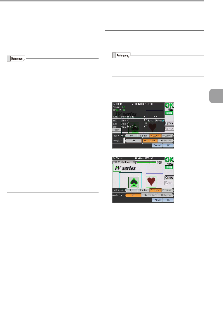
Hiding the statistical information
1
Tap the [View] button.
If the [View] button is not displayed, tap the
[Menu] button at the lower left corner of the
monitor.
The menus of [Tool View] and [Analysis] will be
displayed.
2
Tap the [OFF] button in the [Analysis].
The statistical information becomes hidden.
3
Tap the [OK] button.
The system returns to the Menu ON screen.
5
Operating/Adjusting