
User guide


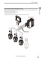
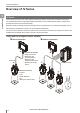
Table Of Contents
- Introduction
- Safety Information for IV Series
- Important Instructions
- Precautions on Regulations and Standards
- Version of the IV Series
- Structure of This Manual
- Contents
- Chapter 1 Getting Started
- Chapter 2 Installation and Connection
- Mounting the Sensor
- Mounting the Monitor
- Cables
- Chapter 3 Basic Operation
- Overview of Screen and Operation
- Basic Operation Flow
- Operation when the Power is Turned on
- Setting to the Factory Default
- Basic Operation for the Monitor
- Chapter 4 Settings Navigator (Setting the Judgment Condition)
- Settings Navigator
- Basic Operation of the Settings Navigator
- 1. Image Optimization (Clearly Image a Target)
- 2. Master Registration (Registering an Image as a Reference for Judgment)
- 3. Tool Settings (Setting the Judgment Method for Targets)
- 4. Output Assignment (Setting Details of Outputting to Output Line)
- Display Method of Extended Functions Menus
- Chapter 5 Operating/Adjusting
- Starting an Operation
- Overview of the Operation Screen
- Names and Functions of the Operation Screen
- Adjusting Thresholds for Judgment
- Tool Auto Tuning (Automatically Adjusting the Judgment Condition)
- Operation flow for the Tool Auto Tuning
- Starting and finishing the Tool Auto Tuning
- Registering the OK/NG images to be used for the Tool Auto Tuning
- Confirming or deleting the images registered for the Tool Auto Tuning
- Tool Auto Tuning by the previous registration information
- Tool Auto Tuning by the registration information file
- Stabilizing the Judgment Process
- Stabilizing the judgment process by taking a clear image of the target
- Imaging the target widely
- Correcting the distorted images due to the installation
- Achieving adequate image brightness
- Achieving good focus
- Reducing the image blur
- Reducing the shininess of the glossy or metal surface
- Adjusting the color tint (for color type only)
- Reducing the effect of illumination variation
- Stabilizing by correcting the misaligned target position
- Stabilizing the position adjustment
- Stabilizing the Outline tool
- ■Basic adjustments
- ■If the outline cannot be detected when the target becomes out of position
- ■If the detection becomes unstable due to the effect of the unwanted outline other than the target
- ■If the target tilts and the outline cannot be detected
- ■If the match rate difference between the high and low-quality-targets is small
- ■If the outline of the target cannot be detected
- Stabilizing the Color Area/Area tool
- Stabilizing the judgment process by taking a clear image of the target
- Shortening the Processing Time
- Chapter 6 Useful Features/Various Functions
- List of the Useful Features
- Displaying the Sensor Setup Menu Screen
- Changeover for a Target (Program Functions)
- Sensor Image History (Confirming the Images whose Status Result is NG)
- Saving the Sensor Settings and Images to a USB Memory
- Setting the Extended Functions of the Sensor
- Setting the Advanced Monitor Information
- Chapter 7 Controlling with Input/Output Line
- Chapter 8 Specifications
- Appendices
- Status Table
- Matching Rate of the Outline Tool and Position Adjustment Tool
- Settings List
- Troubleshooting
- Error Messages
- Remedy when the Monitor cannot be Connected with the Sensor
- Initializing the Network Settings (IP Reset Switch)
- Maintenance
- Index

12
- IV Series User's Manual (Monitor) -
Contents
Backlight.........................................................6-52
Touch Panel Calibration .................................6-52
Monitor Information ........................................6-53
Initialize Monitor .............................................6-53
Update Monitor...............................................6-53
Chapter 7
Controlling with Input/Output Line
Controlling Timing of Judgment with Triggers......7-2
External trigger .................................................7-2
Internal trigger ..................................................7-3
Operating in the shortest cycle .....................7-3
Importing the Status Output.................................7-4
Importing the total status /
total status NG output ......................................7-4
Importing the individual status output of
each detection tool / logic.................................7-5
Changing the timing of the status output..........7-6
Cancelling One-Shot output..........................7-6
Changing Over ....................................................7-7
Registering the Master Image .............................7-8
Clearing Errors ..................................................7-10
Operations when Power of the Sensor is
Turned on ..........................................................7-11
Input Response Time.........................................7-12
Response time for the switch program
input ............................................................7-12
Response time for the external master
registration input .........................................7-12
Response time for the error clear input ......7-12
Description for symbols ..............................7-12
Chapter 8 Specications
Specications ......................................................8-2
Sensor ..............................................................8-2
Intelligent Monitor .............................................8-4
Dimensions ..........................................................8-6
Sensor ..............................................................8-6
Optional parts for the sensor ............................8-7
Dome attachment .........................................8-7
Polarizing lter attachment ...........................8-8
Power I/O cable ............................................8-8
Mounting adapter ..........................................8-8
Front cover....................................................8-8
Bracket..........................................................8-9
Intelligent Monitor ...........................................8-10
Optional parts for the monitor.........................8-12
Monitor power cable ...................................8-12
Protection sheet ..........................................8-12
Stylus ..........................................................8-12
Wall mounting adapter ................................8-12
Panel mounting adapter..............................8-12
DIN mounting adapter.................................8-12
Connection Cable...........................................8-13
Monitor cable ..............................................8-13
Ethernet cable.............................................8-13
Appendices
Status Table ........................................................ A-2
Status table ..................................................... A-2
Displaying and outputting the status result ..... A-4
Displaying and outputting the status result
at the time of position adjustment ................... A-4
Matching Rate of the Outline Tool and
Position Adjustment Tool .................................... A-5
Matching rate at the time of protrusion............ A-5
Cut-off process of the matching rate ............... A-5
Settings List ........................................................ A-6
RUN screen (menu display OFF) .................... A-6
RUN screen (menu display ON)...................... A-6
Sensor Setup Menu screen............................. A-7
Monitor Settings screen .................................. A-9
Sensor Advanced screen .............................. A-11
Sensor Setup screen..................................... A-14
1. Image Optimization ................................ A-14
2. Master Registration................................ A-15
3. Tool Settings .......................................... A-15
4. Output Assignment ................................ A-18
Troubleshooting ................................................ A-19
Error Messages ................................................ A-22
Checking errors by observing
the PWR/ERR indicator light of the sensor ... A-22
Conrming error messages of the monitor .... A-24
Remedy when the Monitor cannot
be Connected with the Sensor ......................... A-28
Remedy when direct connection is
unavailable .................................................... A-28
Remedy when connection via
a network is unavailable ................................ A-29
Conrming the status by observing
the indicator light of the sensor ..................... A-32
LINK/ACT (link/activity) indicator light ........ A-32
STATUS indicator light ............................... A-33
Conrming the status by observing
the SENSOR indicator light of the monitor .... A-34
Other methods of conrming a network
connection ..................................................... A-35
Conrming the existence of
the sensor from the monitor ....................... A-35
If the displayed conrmation
result is “NG” ...................................... A-35
Conrming/Setting the IP address of
the monitor ................................................. A-36
Conrming/Setting the IP address of
the sensor .................................................. A-37
Conrming the router settings.................... A-37
Remedy when data transfer via
FTP is unavailable ..................................... A-38
Initializing the Network Settings
(IP Reset Switch) .............................................. A-40
Settings after initialization ............................. A-40
Connecting method after initialization ........... A-40
For direct connection ......................... A-40
For network connection ..................... A-40
Initializing the network settings ..................... A-40