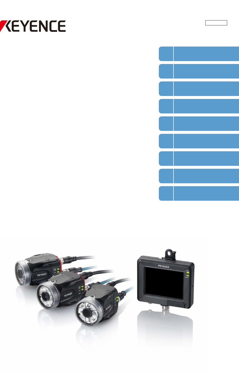
206GB Vision Sensor IV Series User’s Manual (Monitor) Read this manual before use. After you read this manual, keep it in a safe place for future reference.
Introduction Introduction Read this manual before using the product in order to achieve maximum performance. Keep this manual in a safe place after reading it so that it can be used at any time. Symbols The following symbols alert you to important messages. Be sure to read these messages carefully. It indicates a hazardous situation which, if not avoided, will result in death or serious injury. It indicates a hazardous situation which, if not avoided, could result in death or serious injury.
Safety Information for IV Series Safety Information for IV Series General Precautions yyDo not use this product for the purpose to protect a human body or a part of human body. yyThis product is not intended for use as an explosion-proof product. Do not use this product in hazardous location and/or potentially explosive atmosphere. yyYou must verify that the IV Series are operating correctly in terms of functionality and performance before the start and the operation of the IV Series.
Important Instructions Important Instructions Observe the following precautions to prevent malfunction of the IV Series and to ensure that it is used properly. Precautions on use yyThe power of this product and instruments connected to this product must be turned off when the cable is to be installed or removed. Failure to do so may cause an electric shock or a product damage. yyUse this product in the correct supply voltage. Failure to do so may cause a product damage.
Important Instructions Measures to be taken when an abnormality occurs In the following cases, turn the power OFF immediately. Using the IV Series in an abnormal condition could cause fire, electric shock, or malfunction. Contact our office for repair. yyIf water or debris enters the IV Series. yyIf the IV Series is dropped or the case is damaged. yyIf abnormal smoke or odor emanates from the IV Series.
Precautions on Regulations and Standards Precautions on Regulations and Standards For IV-500C/IV-500CA/IV-500M/IV-500MA/IV-150M/IV-150MA/ IV-2000M/IV-2000MA UL Certification This product is a UL/C-UL Listed product. yyUL File No. E301717 yyCategory NRKH, NRKH7 Be sure to consider the following specifications when using this product as a UL/C-UL Listed Product. yyUse a power supply with Class 2 output defined in NFPA70 (NEC: National Electrical Code).
Precautions on Regulations and Standards For IV-M30 UL Certification This product is a UL/C-UL Listed product. yyUL File No. E207185 yyCategory NRAQ, NRAQ7 Be sure to consider the following specifications when using this product as a UL/C-UL Listed Product. yyUse a power supply with Class 2 output defined in NFPA70 (NEC: National Electrical Code). yyThis product is for use on a flat surface of a Type 1 enclosure.
Version of the IV Series Version of the IV Series You can download the most recent operation software for the sensor (IV-150/500/2000) and the monitor (IV-M30) from the KEYENCE web site. Please refer to the description on the homepage for the introduction method. URL : http://www.keyence.com/ Operation software of the sensor (IV-150/500/2000) Version Description R1.00.00 The initial version. R1.01.00 The processing time has been speeded up. R1.10.
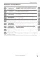
Structure of This Manual Structure of This Manual 1 Getting Started This chapter explains the system configuration and overview of IV Series, package contents, and names and functions of each part. 2 Installation and Connection This chapter explains how to mount the sensor and monitor, and explains connection procedures. 3 Basic Operation This chapter explains the basic operation and operation flow of the IV Series.
Contents Contents Introduction Symbols Cautions Safety Information for IV Series..............................1 General Precautions............................................1 Safety precautions on LED product.....................1 Important Instructions..............................................2 Precautions on use..............................................2 Measures to be taken when an abnormality occurs..................................................................
Contents Chapter 3 Basic Operation Overview of Screen and Operation......................3-2 Basic Operation Flow...........................................3-4 Operation when the Power is Turned on..............3-5 Operation flow when the power is turned on.....3-5 Operation for initial startup of the monitor (Direct Connection)...........................................3-6 Operation for initial startup of the monitor (Network Connection).......................................
Contents 4. Output Assignment (Setting Details of Outputting to Output Line).....4-60 Main screen for the Output Assignment..........4-60 Setting range of the Output Assignment.........4-60 Default value........................................4-60 Setting the Output Assignment.......................4-61 Extended functions for the Output Assignment....................................4-62 Extended functions items for the Output Assignment................................4-62 Logic Settings...............
Contents If the outline of the target cannot be detected..........................................5-39 Stabilizing the Color Area/Area tool................5-39 Basic adjustments................................5-39 If the color you wish to judge cannot be extracted.........................................5-39 If the area search becomes unstable due to unwanted colors being extracted....................................5-39 Shortening the Processing Time........................
Contents Backlight.........................................................6-52 Touch Panel Calibration..................................6-52 Monitor Information.........................................6-53 Initialize Monitor..............................................6-53 Update Monitor...............................................6-53 Chapter 7 Controlling with Input/Output Line Controlling Timing of Judgment with Triggers......7-2 External trigger..................................................
Contents Maintenance...................................................... A-41 Attaching the protection sheet....................... A-41 Replacing the front cover............................... A-41 Index..................................................................
Contents MEMO 14 - IV Series User's Manual (Monitor) -
1 System Configuration........................................1-2 Overview of IV Series.........................................1-4 Checking the Package Contents.......................1-8 Name and Function of Each Part....................1-13 - IV Series User's Manual (Monitor) - 1-1 1 Getting Started Getting Started This chapter explains the system configurations and overview of IV Series, how to check package contents, and the name and function of each part.
System Configuration System Configuration 1 Basic configurations of IV Series Getting Started Connecting the monitor and single sensor IV Series Simulator (IV-Navigator) Intelligent Monitor IV-M30 IVP-Converter Monitor power cable (2m/5m/10m) Monitor cable (2m/5m/10m/20m) Eth ern Sensor IV-500C IV-500CA IV-500M IV-500MA IV-150M IV-150MA IV-2000M IV-2000MA et co mm un USB memory ica tio n Power I/O cable (2m/5m/10m) (Optional) Dome attachment IV-D10 Polarizing filter attachment OP-87436/OP-
System Configuration 1 Connecting the monitor and multiple sensors Ethernet switch Ethernet cable (2m/5m/10m) - IV Series User's Manual (Monitor) - 1-3 Getting Started When the network is connected, the intelligent monitor (IV-M30) can be connected by selecting a single sensor from among multiple sensors. * Each sensor requires the power I/O cable. * IV-M30 requires the power cable. * A single monitor cannot be connected with multiple sensors at the same time.
Overview of IV Series Overview of IV Series 1 IV Series Getting Started The IV Series is an all-in-one “Vision Sensor” featuring a camera, a light, and a controller. This sensor can be attached easily so complicated detection operations such as detecting the shapes of parts with a photoelectric switch can be achieved easily. Operation condition settings require the intelligent monitor (IV-M30) or the IV software IV-Navigator (IV-H1). After setting is completed, the sensor can be operated independently.
Overview of IV Series 1 Using with the IV-Navigator (IV-H1) Getting Started The IV-Navigator has the same functions as the intelligent monitor (IV-M30). For details of operations using the IV-Navigator, refer to “IV Series User's Manual (PC Software)”.
Overview of IV Series 1 Judgment processing flow Getting Started This section describes the basic judgment processing flow of this device. Trigger input BUSY output Total status output Trigger input Imaging Tool processing Status output Save images 1-6 Inputs the imaging startup signal by synchronizing to the target position from a photoelectric switch or PLC. Also, the trigger can be input at a regular interval with an internal trigger function.
Overview of IV Series MEMO 1 Getting Started - IV Series User's Manual (Monitor) - 1-7
Checking the Package Contents Checking the Package Contents 1 Getting Started IV Series are constructed by each following model. Check that all the following packed items are packed for each model you purchased before using.
Checking the Package Contents Front cover (for replacement) yyOP-87440 (2m) yyOP-87441 (5m) yyOP-87442 (10m) yyOP-87461 1 Getting Started Power I/O cable (M12 12pin - strand wire) Mounting screw x 2 Front cover (for replacement) x 1 O-shaped ring (Small x 2, Large x 1) Power I/O cable (M12 12pin - strand wire) x 1 Mounting adapter Hexagon wrench (L-shaped) x 1 yyOP-87460 Instruction Manual x 1 Screw for the mounting adapter x 1 Mounting adapter x 1 Same as accessories for the sensor.
Checking the Package Contents 1 Intelligent Monitor Getting Started yyIV-M30 Stylus x 1 String for hanging the stylus x 1 Monitor x 1 Wall mounting adapter x 1 Screw for the adapter x 2 Hexagon nut x 2 Instruction Manual x 1 Starting Guide x 1 “Name and Function of Each Part” (Page 1-13) “Mounting the Monitor” (Page 2-8) “Cables” (Page 2-12) Optional parts for the monitor Monitor power cable (M8 4pin - strand wire) USB memory (1GB) yyOP-87502 yyOP-87443 (2m) yyOP-87444 (5m) yyOP-87445 (10m) USB m
Checking the Package Contents 1 Wall mounting adapter Getting Started yyOP-87464 Screw for the adapter x 2 Hexagon nut x 2 Wall mounting adapter x 1 Same as accessories for monitors. Optional parts in case of loss/damage.
Checking the Package Contents 1 Communication Cable Getting Started Monitor cable (M12 4pin - M12 4pin) Ethernet cable (M12 4pin - RJ-45) yyOP-87450 (2m) yyOP-87451 (5m) yyOP-87452 (10m) yyOP-87453 (20m) yyOP-87457 (2m) yyOP-87458 (5m) yyOP-87459 (10m) Monitor cable (M12 4pin - M12 4pin) x 1 1-12 Ethernet cable (M12 4pin - RJ-45) x 1 - IV Series User's Manual (Monitor) -
Name and Function of Each Part Name and Function of Each Part Sensor Mounting adapter Use this for mounting and fixing the sensor. “Mounting the Sensor” (Page 2-2) 2 Connector for power I/O cable Connector for connecting the power I/O cable. Use this for supplying the power to the sensor and for connecting with external devices.
Name and Function of Each Part 1 Operation of the indicator light 3 Getting Started Details on operations of the indicator light are shown below. 4 5 2 PWR/ERR Indicates the power supplying status to the sensor and the error status of the sensor. yyGreen (ON)....... Operating. yyGreen (Blink)..... Setting processing. Operation is stopped. Blinks once a second. yyRed (ON)........... Unrecoverable error has occurred. yyRed (Blink)........ Recoverable error has occurred. yy(OFF)................
Name and Function of Each Part 4 Monitor 4 5 6 7 For countermeasures when an error occurred, “Error Messages” (Page A-22). refer to 5 8 1 2 If the monitor cannot correctly connect with the “Remedy when the Monitor sensor, refer to cannot be Connected with the Sensor” (Page A-28). 9 6 LCD monitor/Stylus Displays the operation screen and setup screen. Operates by touching the screen with the stylus. 7 USB connecting connector Connector for connecting the USB memory.
Name and Function of Each Part MEMO 1 Getting Started 1-16 - IV Series User's Manual (Monitor) -
2 Mounting the Sensor..........................................2-2 Mounting the Monitor.........................................2-8 Cables................................................................2-12 - IV Series User's Manual (Monitor) - 2-1 2 Installation and Connection Installation and Connection This chapter explains how to mount the sensor and monitor, and explains connection procedures.
Mounting the Sensor Mounting the Sensor 2 Installation and Connection yyGround (functional ground) the drain cable (FG) of the power I/O cable. yyMount and insulate the sensor. Use the attached mounting adapter to insulate. Sensor case has been grounded. If the sensor is not insulated, the electric potential and noises may cause a damage or malfunction.
Mounting the Sensor Standard range type (color/monochrome) zz 2 500 Installation and Connection Installed distance WD (mm) 600 400 300 200 150 100 50 0 25 50 70 100 130 150 200 210 250 View H (mm) Installed distance WD (mm) Short range type zz 150 100 50 0 10 12 20 30 36 40 View H (mm) Long range type zz Installed distance WD (mm) 2500 2000 1500 1000 500 300 0 45 100 200 300 400 View H (mm) The value of View H and V will be a half of the value on the figures above when using
Mounting the Sensor Mounting the sensor 2 Mounting the sensor onto the mounting adapter Mounting the mounting adapter Installation and Connection Use the mounting adapter (accessory or OP-87460) to mount the sensor. The mounting adapter is mounted with the sensors in the default factory setting. Remove it from the sensor. “Unmounting the sensor” (Page 2-5) Mounting on the wall yyScrew : M3 x 4 Use the commercially available screws which have head thickness of 3 mm or lower.
Mounting the Sensor Unmounting the sensor 2 1 Dismount the screw. Installation and Connection 2 Pull out the stopper of the mounting adapter and unmount the sensor.
Mounting the Sensor 2 Fix the dome attachment with attached Mounting the attachment Using the dome attachment yyDo not remove the front cover of the sensor. yyUse the dome attachment at a correct installation distance. Failure to do so may lose the effect of the dome attachment. yyAdjust the brightness with the dome attachment mounted. “Auto Brightness Adjustment” (Page 4-11) yyFor the color type, adjust the white balance with the dome attachment mounted.
Mounting the Sensor Using the polarizing filter attachment the attached dedicated screws. 2 yyScrew : M2.5 x 2 Use the attached dedicated screws. yyTightening torque : 0.25 to 0.35 N·m Remove the protection sheet (blue) 1 Mount the attachment by aligning the concave part of the polarizing filter attachment with the mounting screw of the front cover of the sensor.
Mounting the Monitor Mounting the Monitor Mounting to a wall 2 Installation and Connection Use the wall mounting adapter (accessories or OP87464). Hang it on the hook with the wall mounting adapter mounted to the monitor, or mount the monitor to the wall mounting adapter mounted on the wall. Hanging on the hook For operation take the monitor from the hook and operate it while holding it in your hands.
Mounting the Monitor 2 Mount the monitor to the wall mounting adapter by aligning the stopper of the wall mounting adapter to the groove on the rear monitor. Unlock the monitor from the wall mounting adapter by pulling toward the unlock button. And slide up to unmount the monitor mounted to the adapter. Unlock Stopper - IV Series User's Manual (Monitor) - 2-9 2 Installation and Connection Slide the monitor down all the way, and confirm that the monitor is locked.
Mounting the Monitor 3 Mount the monitor with the panel adapter Mounting to a panel mounted to the control board from the rear side, and fix it with the screws. Mounting to a panel 1 Connect the power cable and monitor cable to the monitor. “Cables” (Page 2-12) 2 Mount the panel adapter to the monitor and fix it with the attached screws. Strap holder yyScrew : M3, 11 mm long, with 2 washers Use the attached screws. yyTightening torque : 0.27 to 0.
Mounting the Monitor 2 Adjust the position of the DIN mounting Mounting to the DIN rail adapter and the DIN rail by pulling down the stopper of the adapter, and then push up the stopper to lock it. Mounting using DIN mounting adapter 1 Mount the monitor to the DIN mounting adapter. Slide the monitor until the end of the stopper, and confirm that the monitor is locked.
Cables Cables 2 Connecting the power I/O cable of the sensor Installation and Connection 1 Adjust the pins of the connector for the power I/O cable and pin connection of the cable connector, and connect the cable to the sensor. 3 Wire each cable according to its intended purpose.
Cables Wiring color Name Assigning default value Brown DC24V - + side of power Blue 0V - - side of power GND of input-output cable Black OUT1 Total Status (N.O.) White OUT2 BUSY (N.O.) Gray OUT3 Error (N.O.) Orange OUT4 OFF Pink IN1 External trigger ↑ Yellow IN2 OFF Light Blue IN3 OFF Purple IN4 OFF Green IN5 OFF Red IN6 OFF Drain FG - Description 2 Installation and Connection Output assignable function yyTotal Status yyTot. StatusNG yyRUN yyBUSY yyError yyPos.
Cables 2 Specification of I/O circuit and current of the sensor No-voltage input (When the NPN output is selected) +3.
Cables Connecting the power cable of the monitor 2 Align the arrow mark of the power cable and the direction of the front monitor, and connect the cable to the monitor. Installation and Connection 1 3 Wire to the power supply. Brown (DC24V) Monitor power cable (2m/5m/10m) Blue (0V) DC24V Cable specification Brown/Blue : AWG24 Arrow mark 2 Turn the screw-on connector in the clockwise direction to tighten it.
Cables 2 Connecting the sensor and the monitor Installation and Connection Connecting directly Connect the sensor and monitor using the monitor cable. Connecting via network Connect each Ethernet cable to the monitor and sensor. Connect the other side of the Ethernet cable to the Ethernet switch. Ethernet switch Monitor cable (2m/5m/10m/20m) Ethernet cable (2m/5m/10m) For details on connecting the monitor cable, refer to “Connecting the monitor cable/Ethernet cable” (Page 2-17).
Cables Connecting the monitor cable/ Ethernet cable 1 Align the pin connection parts of the monitor cable/Ethernet cable connector with three pins of the cable connector, and connect the cable to the sensor. Align the pins and the pin connection If the connector cable tightening is weak, vibration may loosen the connector and cause bad connections or cable disconnections. Also, the enclosure rating may not be maintained with loose connection.
Cables MEMO 2 Installation and Connection 2-18 - IV Series User's Manual (Monitor) -
3 Basic Operation Overview of Screen and Operation...................3-2 Basic Operation Flow.........................................3-4 Operation when the Power is Turned on..........3-5 Setting to the Factory Default.........................3-12 Basic Operation for the Monitor......................
Overview of Screen and Operation Overview of Screen and Operation This section explains monitor displays and operation. For details of what can be set on each screen and its operation, see to the applicable references. Run screen 3 Basic Operation Images and judges based on the judgment condition.
Overview of Screen and Operation Program list Sets condition to judge a target. “Displaying the Sensor Setup Menu Screen” (Page 6-7) Settings Navigator Sets the program to be used for judgment. “Chapter 4 Settings Navigator (Setting the Judgment Condition)” (Page 4-1) A B Limit Adjustment Adjusts the judgment threshold. “Adjusting Thresholds for Judgment” (Page 5-14) Sensor Advanced Performs the sensor advanced settings.
Basic Operation Flow Basic Operation Flow Mounting, connecting, and wiring the sensor and monitor Mount the sensor and monitor, and then connect and wire the cable. “Chapter 2 Installation and Connection” (Page 2-1) 3 Basic Operation Turning on the power Turn on the power of the sensor and monitor, and then perform the initial startup setting. “Operation when the Power is Turned on” (Page 3-5) Settings Navigator Create the program to be used for operation in [Settings Navigator] (Sensor Setup).
Operation when the Power is Turned on Operation when the Power is Turned on Operation flow when the power is turned on Turn on the power Initial start-up of the monitor yyDirect Connection yyNetwork Connection (2) (4) (5) The Sensor Setup Menu screen opens. Set the (3) activation condition in Settings Navigator. After the setting is completed, operation begins.
Operation when the Power is Turned on Operation for initial startup of the monitor (Direct Connection) 3 1 Turn on the power of the monitor. The screen to select the language opens. Basic Operation 2 Select the language to be displayed on 5 Turn on the power of the sensor. Turn on the power of the sensor before the monitor is restarted by tapping the [OK] button in step 6. 6 Tap the [OK] button. the monitor and tap the [OK] button. The monitor restarts and connects to the sensor.
Operation when the Power is Turned on Operation for initial startup of the monitor (Network Connection) 4 Select the [Network Connection] button and tap the [OK] button. When connecting to a network, let engineers who are knowledgeable about networks handle it. 3 Basic Operation Setting the network address of the monitor 1 Turn on the power of the monitor. The screen to select the language opens. 2 Select the language to be displayed on The Complete Configuration screen opens.
Operation when the Power is Turned on 7 Set the IP Address, Subnet Mask, and Default Gateway individually, and then tap the [OK] button. IP address 3 Basic Operation The system returns to the network setup screen. 8 Tap the [OK] button. Searching for a sensor to be connected Automatically searches for a sensor on the network and connects with it. yyThe search time is about 10 seconds. yySearching range and retrievable number of units are as follows.
Operation when the Power is Turned on When a sensor with no IP address is found zz The confirmation dialog appears. 3 Empty Tap the [Yes] button to copy the network settings of the monitor. When copying is completed, the information screen opens. IP address 3 When multiple sensors are found, select the sensor to be connected with the [<] or [>] button. 4 Connect to the sensor. Tap the [OK] button. The sensor network setup screen opens.
Operation when the Power is Turned on The system returns to the network setup screen for the sensor to be connected. Specifying sensor to be connected by IP address Used when the IP address of the sensor to be connected is defined beforehand. 3 Basic Operation 1 Turn on the power of the sensor. 2 Tap the [Specify Sensor] button. Tap the [Connect] button. yyWhen the monitor is connected with the sensor for the first time, set the polarity of the sensor.
Operation when the Power is Turned on Operation for initial startup of the sensor When the monitor is connected to the sensor in the default setting, the screen to select the polarity (NPN or PNP) opens. After the polarity is selected, set up the sensor in Settings Navigator. For details of the Polarity, refer to “Specification of I/O circuit and current of the sensor” (Page 2-14). 3 Basic Operation 1 Select the Polarity of the sensor and tap the [OK] button. The Sensor Setup Menu screen opens.
Setting to the Factory Default Setting to the Factory Default 3 Tap the [System] button and then the Initializing the sensor Initializes information set in the sensor and uses factory default setting. 3 Basic Operation yyThe following settings will not be initialized. yyPolarity (Switching NPN/PNP) (Page 6-28) yyNetwork Settings (IP Address / Subnet Mask / Default Gateway / Port number (TCP)) (Page 6-31) yyTo initialize the registered programs individually, refer to “Initializing a program” (Page 6-13).
Setting to the Factory Default 4 Tap the [OK] button. Initializing the monitor Initializes information set in the monitor and uses factory default setting. 3 1 Set the menu display of the monitor to ON and tap the [Monitor Settings] button. Initialization begins. After initialization is completed, the initialization completion screen opens. 5 Tap the [OK] button. The Monitor Settings screen opens. 2 Tap the [System] button and then the [Initialize Monitor] button. 3 Tap the [Go] button.
Basic Operation for the Monitor Basic Operation for the Monitor Editing the value with the slider 3 The value of a trigger interval and the threshold of each tool can be edited. This section explains how to edit the value with the slider using an example of a trigger interval in [Internal]. Setting by the [+] / [-] button zz By tapping the [+] / [-] button, the value of a trigger interval increases or decreases (slider slides in accordance with the value changed).
Basic Operation for the Monitor Changing the size of the tool window zz Editing the tool window The tool window displayed when the tool is set in the Settings Navigator can be edited to any size or direction. This section explains how to edit the tool window using an example of [Outline] tool. By touching either side of the tool window, will be displayed. The height or width of or the tool window can be changed by touching and dragging it.
Basic Operation for the Monitor 3 Edit the program name. Inputting characters 3 The programs or tools to be displayed on the monitor can be named arbitrary. This section explains how to input characters using an example of [Program Name]. (1) (2) (3) (4) (5) Basic Operation (6) According to the items to be set, the number of characters, character types, and characters which can be input are different. 1 (7) On the Sensor Setup Menu screen, tap the [Detail] button.
Basic Operation for the Monitor Selecting the file in the USB memory 5 Select the file to be sent. (1) This section explains how to select the file in the USB memory connected to the monitor using an example of [Transfer Program Settings]. (2) 1 On the Sensor Setup Menu screen, tap the 3 (3) (4) (5) (6) (7) (8) Basic Operation [USB Memory] button. (9) (1) Folder display Displays a tree of currently displayed folder. 2 Tap the [Transfer Program Settings] button.
Basic Operation for the Monitor MEMO 3 Basic Operation 3-18 - IV Series User's Manual (Monitor) -
4 Settings Navigator This chapter explains the functions and operations of the [Settings Navigator]. (Setting the Judgment Condition) - IV Series User's Manual (Monitor) - 4-1 4 Settings Navigator (Setting the Judgment Condition) Settings Navigator..............................................4-2 Basic Operation of the Settings Navigator......4-3 1. Image Optimization (Clearly Image a Target).....................................4-6 2.
Settings Navigator Settings Navigator In the Settings Navigator, the setting items of the program required for judging the target with the sensor are set in each step. While sequentially following the steps with navigation buttons, perform the setting using the menu buttons in accordance with the Settings Navigator guide. Navigation button 4 Settings Navigator guide Settings Navigator (Setting the Judgment Condition) Menu button Flow in the Settings Navigator STEP 1.
Basic Operation of the Settings Navigator Basic Operation of the Settings Navigator Starting the Settings Navigator 1 Turn on the power of the sensor and monitor. 6 Perform the following operation. When the program which has not been set zz in step 5 is selected Tap the [Start] button. When the sensor is in the following condition, the Sensor Setup Menu will be displayed. Proceed to step 5.
Basic Operation of the Settings Navigator Settings Navigator screen and operation flow This section explains each setting screen to be displayed in the Settings Navigator and the operation flow. For details of the contents that can set on each setting screen and its operation, refer to the applicable references. A 4 1. Image Optimization Settings Navigator (Setting the Judgment Condition) “1. Image Optimization (Clearly Image a Target)” (Page 4-6) A A 2. Master Registration “2.
Basic Operation of the Settings Navigator Displaying the Settings Navigator guide When the “Navi Guide” is ON zz The settings in the Settings Navigator will be saved and the system returns to the Sensor Setup Menu screen. yyBy tapping the [No] button, the confirmation dialog to cancel the settings appears. By tapping the [Yes] button, the screen closes without saving the settings. yyBy tapping the [Cancel] button, the system returns to the Settings Navigator screen.
1. Image Optimization 2. Master Registration 3. Tool Settings 4. Output Assignment 1. Image Optimization (Clearly Image a Target) Setting the Image Optimization In this section, set the Image Optimization for taking an image of a target. Adjust the image for defining differences in high and low-quality-targets. Trigger Options zz 4 Settings Navigator (Setting the Judgment Condition) A trigger in this manual indicates the timing to start imaging with the built-in camera of the sensor.
1. Image Optimization Trigger Options 2. Master Registration 3. Tool Settings Auto Brightness Adjustment Focus Adjustment 4. Output Assignment Extended functions Main screen for the Image Optimization This section explains the main screen for the Image Optimization. (1) (3) (4) (5) (6) (2) (8) (9) (1) [Back] button The system returns to the Sensor Setup Menu screen. (2) Image taken by the sensor Displays an image taken by the sensor.
1. Image Optimization Trigger Options 2. Master Registration Auto Brightness Adjustment 3. Tool Settings Focus Adjustment 4. Output Assignment Extended functions Setting the Trigger Options A trigger in this manual indicates the timing to start imaging with the built-in camera of the sensor. In the Trigger Options, set the timing to image a target within the field of view of this device. This device can image a target at any timing, and can image continuously.
1. Image Optimization Trigger Options 2. Master Registration 3. Tool Settings Auto Brightness Adjustment Focus Adjustment 4. Output Assignment Extended functions Internal trigger zz Trigger interval Trigger interval (1) Internal trigger Imaging/ internal processing (2) 4 Settings Navigator (Setting the Judgment Condition) (3) Status output (1) The trigger will be input automatically according to the trigger interval settings. (2) Performs the internal processing after the imaging.
1. Image Optimization Trigger Options 2. Master Registration Auto Brightness Adjustment 3. Tool Settings Focus Adjustment When the [Internal] is selected in step 4 zz Start the Settings Navigator. “Starting the Settings Navigator” (Page 4-3) 2 Display the main screen for the Image Optimization. 4 “Settings Navigator screen and operation flow” (Page 4-4) Settings Navigator (Setting the Judgment Condition) 3 Tap the [Trigger Options] button. The screen to set the Trigger Options opens.
1. Image Optimization Trigger Options 2. Master Registration 3. Tool Settings Auto Brightness Adjustment Auto Brightness Adjustment In the Auto Brightness Adjustment, the target can be imaged with an appropriate brightness by automatically adjusting a light intensity, an exposure time and an imaging mode according to the shape and surface condition (color, shininess, material). 1 Start the Settings Navigator. 2 Display the main screen for the Image Optimization.
1. Image Optimization Trigger Options 2. Master Registration Auto Brightness Adjustment 3. Tool Settings Focus Adjustment Focus Adjustment Adjusts the focusing position for clearly imaging the shape of a target. Adjusting the methods differ depending on the type of the sensor connected (manual focusing type/ auto focusing type). 4 Auto focusing type zz Settings Navigator (Setting the Judgment Condition) The focus position is adjusted automatically.
1. Image Optimization Trigger Options 2. Master Registration 3. Tool Settings Auto Brightness Adjustment 5 Adjust the focusing position as needed. When the focusing position is to be zz adjusted automatically again When the [Auto] button is tapped, the focusing position is adjusted automatically again. adjusted manually Adjust the focus by the slider. Extended functions 6 After the setting is completed, tap the [OK] button. The system returns to the main screen for the Image Optimization.
1. Image Optimization Trigger Options 2. Master Registration Auto Brightness Adjustment 3. Tool Settings Focus Adjustment Focus adjustment for the manual focusing type 1 Start the Settings Navigator. 4. Output Assignment Extended functions 6 Turn the focus adjustment screw of the sensor with the attached flathead screwdriver, and adjust the focus until the focus value reaches the peak mark. “Starting the Settings Navigator” (Page 4-3) 4 2 Display the main screen for the Image Optimization.
1. Image Optimization Trigger Options 2. Master Registration 3. Tool Settings Auto Brightness Adjustment Focus Adjustment 4. Output Assignment Extended functions 7 After the setting is completed, tap the [OK] button. The system returns to the main screen for the Image Optimization. The focus indicator indicates the positions that can be focused over the entire area regardless of the imaging area settings (Page 4-17).
1. Image Optimization Trigger Options 2. Master Registration Auto Brightness Adjustment 3. Tool Settings Focus Adjustment 4. Output Assignment Extended functions Extended functions for the Image Optimization Adjust the Image Optimization in the extended functions menu. Items of extended functions for the Image Optimization Items 4 Settings Navigator (Setting the Judgment Condition) Imaging Area Description Default value Setting range Sets the imaging area (image size of the sensor).
1. Image Optimization Trigger Options 2. Master Registration Auto Brightness Adjustment Imaging Area 1 Display extended functions menu for the Image Optimization. “Display Method of Extended Functions Menus” (Page 4-66) 2 3. Tool Settings Tap the [Imaging Area] button. Focus Adjustment 4. Output Assignment Extended functions For details of editing the tool window, refer to “Editing the tool window” (Page 3-15). 4 After the setting is completed, tap the [OK] button.
1. Image Optimization Trigger Options 2. Master Registration Auto Brightness Adjustment 3. Tool Settings Focus Adjustment Extended functions Advanced Brightness Adjustment Lighting 1 Display extended functions menu for the 1 Display extended functions menu for the Image Optimization. “Display Method of Extended Functions Menus” (Page 4-66) 4 4. Output Assignment 2 Tap the [Advanced Brightness Adjustment] Image Optimization.
1. Image Optimization Trigger Options 2. Master Registration 3. Tool Settings Auto Brightness Adjustment Color Filters (color type only) This is disabled for the Color Area tool. 1 Display extended functions menu for the Image Optimization. “Display Method of Extended Functions Menus” (Page 4-66) Focus Adjustment 4. Output Assignment Extended functions Digital Zoom (monochrome type only) 1 Display extended functions menu for the Image Optimization.
1. Image Optimization 2. Master Registration 3. Tool Settings 4. Output Assignment 2. Master Registration ( Registering an Image as a Reference for Judgment) Registers a master image to be a reference for judgment. Main screen for the Master Registration This section explains the main screen for the master image registration. 4 (1) (3) (4) (2) (5) Settings Navigator (Setting the Judgment Condition) (6) (7) (8) (1) [Back] button Returns to the settings screen for the Image Optimization. “1.
1. Image Optimization 2. Master Registration 3. Tool Settings Register Live Image as Master Registering the master image 4. Output Assignment Extended functions 7 Tap the [OK] button. 1 Start the Settings Navigator. “Starting the Settings Navigator” (Page 4-3) 2 Display the main screen for the Master Registration. “Settings Navigator screen and operation flow” (Page 4-4) of judgment on the imaging position. 4 Tap the [Register Live Image as Master] button.
1. Image Optimization 2. Master Registration Register Live Image as Master 3. Tool Settings Extended functions Extended functions for the Master Registration Items of extended functions for the Master Registration 4 4. Output Assignment Select Img From Image History zz Settings Navigator (Setting the Judgment Condition) Registers an image of the image history in the memory of the sensor as a master image.
1. Image Optimization 2. Master Registration 3. Tool Settings Register Live Image as Master 4. Output Assignment Extended functions 4 Check the image displayed on the monitor and tap the [Register] button. 4 Settings Navigator (Setting the Judgment Condition) The confirmation dialog appears. If the imaging area of the loaded image is different, the confirmation dialog appears. If an area that has not been imaged is registered, the area will be displayed in black. 5 Tap the [OK] button.
1. Image Optimization 2. Master Registration Register Live Image as Master 3. Tool Settings Extended functions Registering from the image in the USB memory Select the batch backup file (*.iva) or image capture file (*.ivp) stored in USB memory, and register as a master image. 4 4. Output Assignment 5 Select the image to be registered as a master image and tap the [Register] button. Select the image When using a batch backup file (*.
1. Image Optimization 2. Master Registration 3. Tool Settings Register Live Image as Master When using an image capture file (*.ivp) 5 “Saving the image history individually” (Page 6-20) 4. Output Assignment Extended functions Check the image displayed on the monitor and tap the [Register] button. 1 Connect the USB memory which stores the image capture files (*.ivp) to the USB port.
1. Image Optimization 2. Master Registration Register Live Image as Master 3. Tool Settings Extended functions 5 Set the tool window to be a reference of Brightness correction For the Color Area tool of the color type, this will be disabled. 4 4. Output Assignment brightness correction and tap the [OK] button. 1 Display the extended functions menu for the Master Registration.
1. Image Optimization 2. Master Registration 3. Tool Settings Register Live Image as Master 4. Output Assignment Extended functions 7 Tap the [Before Corr]/[After Corr] button and check the operation status before brightness correction and status after brightness correction. 4 Settings Navigator (Setting the Judgment Condition) 8 Tap the [Back] button. The system returns to the settings screen for the Brightness Correction. 9 After the setting is completed, tap the [OK] button.
1. Image Optimization 2. Master Registration 3. Tool Settings 4. Output Assignment 3. Tool Settings ( Setting the Judgment Method for Targets) 4 Settings Navigator (Setting the Judgment Condition) In this section, set the tool to judge whether a target is high-quality-target or low-quality-target in the master image. The aspects of a target registered as a master image are set as a high-quality-target.
1. Image Optimization 2. Master Registration Color Area/Area tool zz 3. Tool Settings 4. Output Assignment Position Adjustment tool zz A tool to correct the differences in positioning (position gap) of a target to be examined. The position adjustment is used with other detection tools.
1. Image Optimization 2. Master Registration 3. Tool Settings 4. Output Assignment Main screen for the Tool Settings This section explains the main screen for the Tool settings. 4 (1) (2) (4) (5) (3) (6) (7) Settings Navigator (Setting the Judgment Condition) (8) (9) (10) (11) (12) (1) [Back] button Returns to the Master Registration screen. “2.
1. Image Optimization 2. Master Registration Adding/Editing/Deleting a tool 3. Tool Settings 4. Output Assignment Editing a tool Edits the settings of a tool which has already been set. Adding a tool 1 Select a tool to edit the settings. Newly sets a tool. 1 Tap the [Add Tool] button. 4 2 Tap the tool to be added. Settings Navigator (Setting the Judgment Condition) yyIf no tools are set, only the [Add Tool] button is displayed.
1. Image Optimization Outline tool 2. Master Registration Color Area/Area tool 3. Tool Settings Position Adjustment tool 4. Output Assignment Extended functions Outline tool Setting items for the Outline tool Items ¨ Rect Fine Tune Outline Selects the window shape to specify an area of the target to be detected. Entire yyEntire Specifies an area to search the Specifies the entire imaging area as a (Without position outline of a target. By specifying adjustment) search region.
1. Image Optimization Outline tool 2. Master Registration Color Area/Area tool 3. Tool Settings Position Adjustment tool 4. Output Assignment Extended functions 6 Select a tool window shape. Setting the Outline tool 1 Start the Settings Navigator. “Starting the Settings Navigator” (Page 4-3) 2 Display the main screen for the Tool settings. “Settings Navigator screen and operation flow” (Page 4-4) 4 ¡ Circle [Outline] button.
1. Image Optimization Outline tool 2. Master Registration Color Area/Area tool 3. Tool Settings Position Adjustment tool 12 Tap the [Limit Adjustment] button. 4. Output Assignment Extended functions 14 Adjust the threshold of anomaly detection by checking the matching rate. If the matching rate of the high-quality-target is higher than 90 and if the matching rate of the lowquality-target is lower than 40, set the threshold to 65 which is an intermediate value between 40 and 90.
1. Image Optimization Outline tool 2. Master Registration Color Area/Area tool 3. Tool Settings Position Adjustment tool 4. Output Assignment Extended functions Setting a search region Settings for disabling outlines When a range of the search region is to be specified, perform the following procedures. Perform the following procedures to delete an unnecessary extracted outline in the tool window. 1 Tap the [Search Region] button. 1 Tap the [Fine Tune Outline] button.
1. Image Optimization Outline tool 2. Master Registration Color Area/Area tool 3. Tool Settings Position Adjustment tool 4. Output Assignment Extended functions Setting a sensitivity According to the target, perform the following procedures when the extraction sensitivity of an outline is selected. 1 Tap the [Fine Tune Outline] button. 4 Settings Navigator (Setting the Judgment Condition) The outline cannot be extracted The Settings Navigator guide opens. Tap the [OK] button.
1. Image Optimization Outline tool > Extended functions 2. Master Registration Color Area/Area tool 3. Tool Settings Position Adjustment tool 4. Output Assignment Extended functions Extended functions for the Outline tool Items Margin Search Algorithm Setting range Sets a range of the rotating direction to search an outline of the target. The system judges NG if an angle of the target exceeds its rotation range even if the target is the same shape.
1. Image Optimization 2. Master Registration Outline tool > Extended functions 3. Tool Settings Color Area/Area tool Rotation Range 1 Display the extended functions menu of the Outline tool. “Display Method of Extended Functions Menus” (Page 4-66) 2 Tap the [Rotation Range] button. 4 4. Output Assignment Position Adjustment tool Extended functions 5 After the setting is completed, tap the [OK] button. The system returns to the main screen for the Outline tool settings.
1. Image Optimization Outline tool > Extended functions 2. Master Registration Color Area/Area tool 3. Tool Settings Position Adjustment tool 4. Output Assignment Extended functions Tool Name 1 Display the extended functions menu of the Outline tool. “Display Method of Extended Functions Menus” (Page 4-66) 2 Tap the [Tool Name] button. 4 Settings Navigator (Setting the Judgment Condition) The screen to set the tool name opens. 3 Input an arbitrary name.
1. Image Optimization Outline tool 2. Master Registration Color Area/Area tool 3. Tool Settings Position Adjustment tool 4. Output Assignment Extended functions Color Area/Area tool Setting items for the Color Area/Area tool Items Description Setting range Default value yy¨ Rect Specifies with the rectangular window. An arbitrary size, position, and angle can be specified with stylus. 4 yy¡ Circle Specifies with the circular window. An arbitrary size and position can be specified with stylus.
1. Image Optimization Outline tool Items 2. Master Registration Color Area/Area tool Description 3. Tool Settings 4. Output Assignment Position Adjustment tool Extended functions Setting range Default value yyExtraction Area Sets the upper and the lower limit of brightness in a range within 0 to 255 with the tapped brightness as a Tap brightness to be extracted reference. Brightness Extraction (No extraction) on the master image and set yyUndo (For monochrome type) the extraction range.
1. Image Optimization Outline tool 2. Master Registration Color Area/Area tool 3. Tool Settings Position Adjustment tool Setting the Color Area/Area tool 4. Output Assignment Extended functions 6 Select a tool window shape. 1 Start the Settings Navigator. “Starting the Settings Navigator” (Page 4-3) 2 Display the main screen for the Tool settings.
1. Image Optimization Outline tool 2. Master Registration Color Area/Area tool 11 Set the area to be the target to extract. For color type zz 3. Tool Settings Position Adjustment tool 4. Output Assignment Extended functions For monochrome type zz Tap the [Brightness Extraction] button. Tap the [Color Extraction] button. 4 The tapped color will be extracted. yyIf the areas of color that have not been extracted are tapped repeatedly, the extraction range can be added.
1. Image Optimization Outline tool 2. Master Registration Color Area/Area tool 3. Tool Settings Position Adjustment tool 12 Tap the [Limit Adjustment] button. 4. Output Assignment Extended functions 15 Set the upper limit as needed. “Setting the upper limit” (Page 4-46) 16 After the setting is completed, tap the [OK] button. The system returns to the main screen for the Color Area/Area tool settings. 4 17 Tap the [OK] button.
1. Image Optimization Outline tool 2. Master Registration Color Area/Area tool Mask settings Perform the following procedures if a mask region is to be specified in the tool window. 3. Tool Settings Position Adjustment tool 4. Output Assignment Extended functions 5 Set the position, size, and angle of the mask shape in accordance with the target. Set mask shape 1 Tap the [Mask] button 4 2 Tap the [Add Mask] button. 6 After the setting is completed, tap the [OK] button.
1. Image Optimization Outline tool 2. Master Registration Color Area/Area tool 3. Tool Settings Position Adjustment tool 9 Select the cutting shape and tap the [OK] button. 4. Output Assignment Extended functions Setting the upper limit To perform the OK/NG judgment when an area of the target is wider than an area of a high-qualitytarget, perform the following procedures. 1 Tap the [Upper Limit] button.
1. Image Optimization Outline tool 2. Master Registration Color Area/Area tool 3. Tool Settings Position Adjustment tool 4. Output Assignment Extended functions 4 Adjust the threshold of anomaly detection by checking the matching rate. 4 Settings Navigator (Setting the Judgment Condition) Matching rate Threshold (upper limit) Threshold (lower limit) yyJudged OK when the matching rate is within threshold range, and NG when it is outside the range.
1. Image Optimization Outline tool 2. Master Registration 3. Tool Settings Color Area/Area tool > Extended functions 4.
1. Image Optimization Outline tool 2. Master Registration Color Area/Area tool > Extended functions Advanced Color Extraction/ Advanced Brightness Extraction 1 Display the extended functions menu of the Color Area/Area tool. “Display Method of Extended Functions Menus” (Page 4-66) 3. Tool Settings 4. Output Assignment Position Adjustment tool Extended functions Tool Name 1 Display the extended functions menu of the Color Area/Area tool.
1. Image Optimization Outline tool 2. Master Registration 3. Tool Settings Color Area/Area tool > Extended functions Position Adjustment tool Extended functions 5 Extract the color/brightness range to be judged. Fixed Reference Area Extract from the Live image zz Select [Enable] if the color/brightness to be judged in the master image cannot be detected. 4 4. Output Assignment Tap the [Color Extraction]/[Brightness Extraction] button.
1. Image Optimization Outline tool 2. Master Registration Color Area/Area tool 3. Tool Settings 4. Output Assignment Position Adjustment tool Extended functions Position Adjustment tool If there are varies of the position determining of the target, the position to be judged is also declined from the tool window and cannot be judged correctly.
1. Image Optimization Outline tool 2. Master Registration Color Area/Area tool 3. Tool Settings Position Adjustment tool 4. Output Assignment Extended functions Setting items for the Position Adjustment tool Items Setting range Window Shape yy¨ Rect Specifies with the rectangular window. An arbitrary size, position, and angle Select a shape of the window can be specified with stylus. to specify the range of a target to be position adjustment yy¡ Circle Specifies with the circular window.
1. Image Optimization Outline tool 2. Master Registration Color Area/Area tool Setting the Position Adjustment tool 3. Tool Settings Position Adjustment tool 4. Output Assignment Extended functions 6 Select a tool window shape. 1 Start the Settings Navigator. “Starting the Settings Navigator” (Page 4-3) 2 Display the main screen for the Tool settings. “Settings Navigator screen and operation flow” (Page 4-4) 4 ¡ Circle [Pos.Adj.] button.
1. Image Optimization Outline tool 2. Master Registration Color Area/Area tool 3. Tool Settings Position Adjustment tool 11 Adjust the outline as needed. “Settings for disabling outlines” (Page 4-55) “Setting a sensitivity” (Page 4-56) 4. Output Assignment Extended functions 14 Adjust a threshold to judge whether or not the position adjustment is succeeded by checking the matching rate. 12 Tap the [Limit Adjustment] button.
1. Image Optimization Outline tool 2. Master Registration Color Area/Area tool 3. Tool Settings Position Adjustment tool 4. Output Assignment Extended functions Setting a search region Settings for disabling outlines To limit a range (adjusting range of position adjustment) to search a target to be a reference, set it in the search region setting. When a range of the search region is to be specified, perform the following procedures.
1. Image Optimization Outline tool 2. Master Registration Color Area/Area tool 3. Tool Settings Position Adjustment tool 4. Output Assignment Extended functions Setting a sensitivity According to the target, perform the following procedures when the extraction sensitivity of an outline is selected. 1 Tap the [Fine Tune Outline] button. 4 Settings Navigator (Setting the Judgment Condition) The outline cannot be extracted The Settings Navigator guide opens. Tap the [OK] button.
1. Image Optimization Outline tool Color Area/Area tool 2. Master Registration 3. Tool Settings Position Adjustment tool > Extended functions 4. Output Assignment Extended functions Extended functions for the Position Adjustment tool Items Rotation Range Default value Setting range Sets a range to adjust the position to the rotating direction. The status result of position adjustment is NG without adjusting the position if an angle of a target exceeds its rotation range.
1. Image Optimization Outline tool 2. Master Registration Color Area/Area tool 3. Tool Settings Position Adjustment tool 4. Output Assignment Extended functions Extended functions for the Tool settings Items of extended functions for the Tool settings Items 4 Copy Tool Description Setting range Default value - - Settings Navigator (Setting the Judgment Condition) Copies a tool which has been set, and pastes it to the same position. This is for outline tool and color area/area tool.
MEMO 4 Settings Navigator (Setting the Judgment Condition) 4-59 - IV Series User's Manual (Monitor) -
1. Image Optimization 2. Master Registration 3. Tool Settings 4. Output Assignment 4. Output Assignment ( Setting Details of Outputting to Output Line) Set the output items to be assigned to the output line (OUT1 to OUT4). “Connecting the power I/O cable of the sensor” (Page 2-12) “Chapter 7 Controlling with Input/Output Line” (Page 7-1) 4 Main screen for the Output Assignment Setting range of the Output Assignment Setting range Description OFF Do not output.
1. Image Optimization 2. Master Registration 3. Tool Settings Output Assignment 4. Output Assignment Extended functions Setting the Output Assignment 1 Start the Settings Navigator. “Starting the Settings Navigator” (Page 4-3) 2 Display the main screen for the Output Assignment. 4 “ Settings Navigator screen and operation flow” (Page 4-4) Settings Navigator (Setting the Judgment Condition) 3 Tap the item name of output line to perform output assignment and select the output item.
1. Image Optimization Output Assignment 2. Master Registration 3. Tool Settings 4. Output Assignment Extended functions Extended functions for the Output Assignment Extended functions items for the Output Assignment Items Description Settings Navigator (Setting the Judgment Condition) Logic Total Status Conditions 4-62 Default value Assigns the logical operation results of each detection tool to the output function. Up to 4 items, Logic 1 to 4, can be defined.
1. Image Optimization 2. Master Registration 3. Tool Settings 4. Output Assignment Output Assignment Logic Settings 1 Display the extended functions menu for Extended functions 5 Select items to be integrated into the logic. the Output Assignment. “Display Method of Extended Functions Menus” (Page 4-66) 2 Tap the [Logic Settings] button. 4 The Logic Settings screen opens. 3 Tap the number which the logic judgement condition is to be defined.
1. Image Optimization Output Assignment 2. Master Registration 3. Tool Settings Extended functions 6 When the setting is completed, tap the Logic : OR zz [OK] button. Tool A Tool B Tool C (Inverse) Logic 1 to 4 The system returns to the Logic Settings screen. 7 Tap the [Close] button. The system returns to the main screen for the Outline tool settings. Image of logic output when the Logic is [OR] 4 4.
1. Image Optimization 2. Master Registration 3. Tool Settings Output Assignment Total Status Conditions 1 Extended functions Any Tools OK zz Display the extended functions menu for the Output Assignment. “Display Method of Extended Functions Menus” (Page 4-66) 2 4. Output Assignment Tap the [Total Status Conditions] button. When any of the detection tools was OK, the total status output function turns ON.
Display Method of Extended Functions Menus Display Method of Extended Functions Menus 4 In each setting for Settings Navigator, the extended functions menu will be displayed by tapping the < > extended functions display button at the lower left on the screen. This section explains how to display the extended functions menu using an example of the Image Optimization screen. For details of extended functions menu, refer to details in each step.
5 Operating/Adjusting This chapter explains the procedures for starting the operation, the names and functions of each part and the adjustment procedures to fully utilize the judgment ability of the IV Series. - IV Series User's Manual (Monitor) - 5-1 5 Operating/Adjusting Starting an Operation.........................................5-2 Overview of the Operation Screen....................5-3 Names and Functions of the Operation Screen.........................................
Starting an Operation Starting an Operation Starts an operation in accordance with the program created with the Settings Navigator. The sensor can be independently operated. Turning on the power and starting an operation 5 Exiting the sensor settings and starting an operation 1 Turn on the power of the sensor and monitor. 1 Exit the settings of the sensor, such as Settings Navigator. 2 Confirm that the operation screen opens.
Overview of the Operation Screen Overview of the Operation Screen Start screen Menu OFF (Page 5-4) 5 Menu ON (Page 5-4) (Page 5-5) Hides the title and menu button, and displays the entire image. Changes the display magnification of an image. Display setting screen Selects the [Tool View] and [Analysis] menu, and set the information to display on the monitor. Statistics display screen Histogram display screen (Page 5-10) (Page 5-12) Displays the statistical information of the status result.
Names and Functions of the Operation Screen Names and Functions of the Operation Screen In the operation screen, the displayed items will be different depending on the ON/OFF of the menus. Menu Screen Menu OFF zz (8) (1) (2) (10) (11) (3) 5 Menu ON zz (9) (9) (8) (1) (2) (10) (11) (3) (4) (4) (5) (5) (12) (13) (14) Operating/Adjusting (7) (6) (15) (1) Title Displays the device name (Page 6-29), program number (Page 6-7), and program name of the sensor (Page 6-12).
Names and Functions of the Operation Screen (11) Condition Display Displays the Condition of the monitor. ......... Indicates “Running”. ......... Indicates “Test mode”. The status result will not be output. (12) [Trig] button Displayed when an external trigger is set. A trigger is issued by each tap on a button. This button is used when the external trigger cannot be input. The button can be set to be displayed or hidden.
Names and Functions of the Operation Screen Enlarging the image display In the full-screen mode, the display magnification of images can be changed. 1 Switch the display to the full-screen mode. “Switching the display to the full-screen mode” (Page 5-5) 2 Change the magnification ratio to the desired 5 ratio by tapping the or button.
Names and Functions of the Operation Screen Selecting a display method for tools When the [View] button is tapped on the Menu ON screen, the menus of [Tool View] and [Analysis] are displayed. If one of the display methods for [Tool View] is selected and the [OK] button is tapped, the display on the monitor changes in accordance with the selected display method. Display methods for tools Depending on the type of the sensor (color or monochrome type), selectable display methods are different.
Names and Functions of the Operation Screen For monochrome type Process 1 zz OFF zz Outside the tool window Inside the tool window 5 Compared to when the [Window] is selected, the following are different. The rest are the same. Operating/Adjusting Selected tool yyOutline tool Displays inside the tool window in monochrome, and outside of the tool window in color. Indicates the recognized outline with a series of points in green (OK) or red (NG).
Names and Functions of the Operation Screen Process zz Process 2 zz Outside the search region Inside the search region Selected tool yyOutline tool Indicates the recognized outline with a series of points in green (OK) or red (NG). yyArea tool Displays the extracted region in green (OK) or red (NG). If the brightness correction has been set, the inside the tool window will be displayed with the corrected brightness and outside the tool window will be displayed with the brightness before correction.
Names and Functions of the Operation Screen Contents of the statistical information are as follows. Displaying the statistical information When the [View] button is tapped on the Menu ON screen, the menus of [Tool View] and [Analysis] are displayed. If the [Statistics] button in the [Analysis] is selected, the statistical information of judgment is displayed. 5 Displaying the statistical information Operating/Adjusting 1 Tap the [View] button.
Names and Functions of the Operation Screen (7) OUT information Displays the latest status results of items which are assigned to an output line (OUT1 to OUT4) (Page 4-60). 3 Tap the [OK] button. The system returns to the Menu ON screen. 1 Tap the [View] button. If the [View] button is not displayed, tap the [Menu] button at the lower left corner of the monitor. The menus of [Tool View] and [Analysis] will be displayed. 2 Tap the [OFF] button in the [Analysis].
Names and Functions of the Operation Screen Contents of the histogram are as follows. Displaying the histogram When the [View] button is tapped on the Menu ON screen, the menus of [Tool View] and [Analysis] are displayed. If the [Histogram] button in the [Analysis] is selected, the matching rate of the selected tool is displayed as a histogram. 5 Displaying the histogram Operating/Adjusting If the [View] button is not displayed, tap the [Menu] button at the lower left corner of the monitor.
Names and Functions of the Operation Screen (7) Threshold Displays the threshold for the selected tool. yyThe upper limit of the judgment processing count display for the judgment record is 999999. The values display stop updating when the upper limit is reached. yyThe upper limit of the histogram is 999999. The values display stop updating when the upper limit is reached. yyThe histogram and judgement records are reset under the following conditions.
Adjusting Thresholds for Judgment Adjusting Thresholds for Judgment The method for manually adjusting the threshold while in the Test mode. The threshold adjustment can be started by the [Limit Adjustment] button in the tool settings of the Settings Navigator. 5 Adjust the threshold by checking the matching rate.
Tool Auto Tuning (Automatically Adjusting the Judgment Condition) Tool Auto Tuning ( Automatically Adjusting the Judgment Condition) The Tool Auto Tuning is a function to automatically adjust the judgment condition for the detection tool and the judgment threshold for each tool by using multiple high-quality-targets (OK images) and lowquality-targets (NG images). There are three methods to register the image to be used for Tool Auto Tuning.
Tool Auto Tuning (Automatically Adjusting the Judgment Condition) Operation flow for the Tool Auto Tuning Displays the main screen for Tool Auto Tuning from the Sensor Setup Menu screen. Start yyThe position adjustment tool is not a target for Tool Auto Tuning. yyThe Color Area/Area tools with the [Fixed Reference Area] set as [Enable] are excluded from a Tool Auto Tuning target. Select the tool 5 1 Display the Sensor Setup Menu screen.
Tool Auto Tuning (Automatically Adjusting the Judgment Condition) Use the registered information file 4 Select a starting method of Tool Auto Tuning. zz Register from the beginning zz 5 Select the registration source of the image to be registered to the Tool Auto Tuning and register the image. If the previous registration information has been saved in the monitor, a confirmation dialog asking whether or not to discard the previous registration information appears.
Tool Auto Tuning (Automatically Adjusting the Judgment Condition) 6 After the registration is completed, tap the [Save] button. Registering the OK/NG images to be used for the Tool Auto Tuning Registering the images taken in the Test mode Registers the image as an OK or an NG image to perform tuning while preparing the multiple high and low-quality-target and checking the images imaged. 5 1 Display the main screen for Tool Auto Tuning. The confirmation dialog appears.
Tool Auto Tuning (Automatically Adjusting the Judgment Condition) For Color Area tool (color type) zz yyBy tapping the [Undo] button, the previous operation can be cancelled. yyTo change the color of extraction target, tap the [Clear] button and tap the color to be the reference of judgment again. After the setting is completed, tap the [Register] button. The auto tuning will be performed and the OK or NG image will be displayed. If the [AutoTune as OK] is tapped, the information screen opens.
Tool Auto Tuning (Automatically Adjusting the Judgment Condition) 5 Check the changes in settings after the auto tuning is performed, and tap the [OK] button. Changed settings 5 Operating/Adjusting If the auto tuning has failed, follow the message to change the tool settings or the image to be registered. Registering the images from the image history saved in the sensor Registers the image as an OK or an NG image to perform tuning while checking the images loaded from the Sensor Image History.
Tool Auto Tuning (Automatically Adjusting the Judgment Condition) For Outline tool zz For Area tool (monochrome type) zz The auto tuning will be performed and the OK or NG image will be displayed. If the [AutoTune as OK] is tapped, the information screen opens. By tapping the [OK] button, the setup screen for the color extraction area opens.
Tool Auto Tuning (Automatically Adjusting the Judgment Condition) 5 Check the changes in settings after the auto tuning is performed, and tap the [OK] button. Changed settings 5 Operating/Adjusting If the auto tuning has failed, follow the message to change the tool settings or the image to be registered. The type of an image to be registered will be displayed on the upper right on the screen. yy : Registers as an OK image. yy : Registers as an NG image.
Tool Auto Tuning (Automatically Adjusting the Judgment Condition) 5 When the batch backup file (*.iva) is selected, tap the image history to be the OK or NG image and tap the [Zoom] button. For Color Area tool (color type) zz Select the image The selected image will be enlarged. [AutoTune as OK] or [AutoTune as NG] button. yyWhen a batch backup file (*.iva) has been selected, you can check the other images in enlarged display by tapping the [<]/[>] button.
Tool Auto Tuning (Automatically Adjusting the Judgment Condition) For Area tool (monochrome type) zz 5 Operating/Adjusting If the [AutoTune as OK] is tapped, the information screen opens. By tapping the [OK] button, the setup screen for the brightness extraction area opens. If the extraction area is inappropriate, tap the brightness to be the reference of judgment, or operate the slider and expand/reduce the brightness area to be extracted.
Tool Auto Tuning (Automatically Adjusting the Judgment Condition) Confirming or deleting the images registered for the Tool Auto Tuning Confirm or delete the OK/NG images registered for the Tool Auto Tuning. 1 Display the main screen for the Tool Auto Tuning. “Starting and finishing the Tool Auto Tuning” (Page 5-16) 5 2 Tap the [Confirmation of Registered Image] Operating/Adjusting button. 3 Confirm or delete the OK/NG image. yy[First]................. Displays the first image. yy[<].............
Tool Auto Tuning (Automatically Adjusting the Judgment Condition) Tool Auto Tuning by the previous registration information 5 Operating/Adjusting When the information of Tool Auto Tuning performed before turning off power of the monitor or before disconnecting with the sensor (previous registration information) is used, the Tool Auto Tuning can be performed skipping the OK/NG image registration process.
Tool Auto Tuning (Automatically Adjusting the Judgment Condition) 4 Tap the [Use the previous registered image] 7 After the registration is completed, tap the button. [Save] button. Re-adjustment is performed by using the previous registration information. The confirmation dialog appears. 5 Check the changes made by the re-adjustment and tap the [OK] button. 8 Tap the [OK] button. Operating/Adjusting The information dialog appears.
Tool Auto Tuning (Automatically Adjusting the Judgment Condition) Tool Auto Tuning by the registration information file 5 Operating/Adjusting When the registration information file (*.ivt), which contains the Tool Auto Tuning images and criteria information saved at the end of the previous Tool Auto Tuning is used, the Tool Auto Tuning can be performed skipping the OK/NG image registration process.
Tool Auto Tuning (Automatically Adjusting the Judgment Condition) 5 Tap the [Use the registered information file] 7 Tap the [Go] button. button. The import screen for registration information file appears. Re-adjustment is performed by using the registered information file. 5 Operating/Adjusting 6 Select the registered information file (*.ivt) and tap the [OK] button. Select the file to be imported The information dialog appears.
Tool Auto Tuning (Automatically Adjusting the Judgment Condition) 10 After the registration is completed, tap the [Save] button. 5 The confirmation dialog appears. Operating/Adjusting 11 Tap the [OK] button. Adjusted results will be reflected and the information dialog appears. 12 Tap the [OK] button. By tapping the [Saving to the USB memory] button, the result of Tool Auto Tuning can be saved in the USB memory as a registration information and can be reused.
Tool Auto Tuning (Automatically Adjusting the Judgment Condition) MEMO 5 Operating/Adjusting - IV Series User's Manual (Monitor) - 5-31
Stabilizing the Judgment Process Stabilizing the Judgment Process This section explains how to adjust the device when the judgment process is not stable. To stabilize the judgment process, it is necessary to take a clear image of the target and adjust the detection tool such that it functions in a stable manner.
Stabilizing the Judgment Process Correcting the distorted images due to the installation If the sensor is not installed just in front of the target due to the sensor installation restrictions and/or to prevent a shine on the target’s surface, the target image may become trapezoidally distorted. The tilt correction corrects these images and displays them without distortion.
Stabilizing the Judgment Process Achieving good focus Reducing the image blur Adjusting the focus is required to clearly image of the target. For the auto focus type, focus can be adjusted easily in the Auto Focus Adjustment. For the manual focus type, the focus can be adjusted while confirming the image and focus indicator. “Focus Adjustment” (Page 4-12) 5 If the image is blurred by imaging a moving target, the image blurring can be corrected by shortening the exposure time (shutter time).
Stabilizing the Judgment Process Reducing the shininess of the glossy or metal surface Glossy and/or metal surface may reflect the built-in light into the camera. Since mirror reflection has a high-light intensity, the amount of light received will be saturated and the surface will shine. This section explains how to reduce the shininess. Using the Auto Brightness Adjustment Use the polarizing filter attachment (OP-87436/ OP-87437).
Stabilizing the Judgment Process Adjusting the color tint (for color type only) Adjust the white balance if the color tint of the color type image is different from that of the target. “White Balance (for color type only)” (Page 6-41) Reducing the effect of illumination variation 5 Operating/Adjusting If the detection is not stable due to the ambient light from the surroundings where the sensor is installed, the effect of the illumination variation can be reduced by the brightness correction function.
Stabilizing the Judgment Process Stabilizing the position adjustment This section explains how to adjust when the position adjustment is not stable. “Position Adjustment tool” (Page 4-51) If the target tilts and the position adjustment becomes unstable Search region Rotation range Basic adjustments Set the position adjustment window as large as possible by selecting a part that contains a unique shape.
Stabilizing the Judgment Process If the outline of the reference target cannot be detected 5 Operating/Adjusting yyIf the contrast of the target is low, the outline may not be extracted. Set the extraction sensitivity to [High]. “Setting a sensitivity” (Page 4-56) If the process remain unstable even after setting the extraction sensitivity to [High], it is necessary to adjust the exposure condition for the target.
Stabilizing the Judgment Process If the target tilts and the outline cannot be detected If the match rate difference between the high and low-quality-targets is small Adjust the search algorithm. If there is no difference between the match rate for high and low-quality-target, select the [High Accuracy]. This will result in better judgment accuracy. However, the processing time becomes longer.
Shortening the Processing Time Shortening the Processing Time 5 Operating/Adjusting This section explains how to adjust the device to shorten the processing time. To shorten the processing time, perform adjustments to shorten the processing times of the imaging process and the detection tools.
Shortening the Processing Time Shortening the imaging processing time Imaging Area zz The processing time can be shortened by adjusting the imaging area. Entire imaging area (default value) Reduce the imaging area Shortening the processing time of each tool Shortening the processing time of the Outline tool The processing time can be shortened by adjusting the settings for the search region, rotation range, and search algorithm.
Shortening the Processing Time Shortening the processing time of the Color Area/Area tool Shortening the processing time of the position adjustment The processing time can be shortened by adjusting the window shape settings. When the position adjustment is performed, the processing time can be shortened by adjusting the search region settings or rotation range settings.
6 Useful Features/ Various Functions This chapter explains the useful features of the sensor and the monitor. The Sensor Setup Menu screen, the Sensor Advanced screen, and the Monitor Settings screen are also explained. - IV Series User's Manual (Monitor) - 6-1 6 Useful Features/Various Functions List of the Useful Features................................6-2 Displaying the Sensor Setup Menu Screen.....6-7 Changeover for a Target (Program Functions)..........................................
List of the Useful Features List of the Useful Features Useful features while running Items Things you want to do 6 Useful Features/Various Functions Analysis Reference page Up to 32 types (products) of products can be registered and loaded. 6-8 Assign a name to the settings of each product for easy Program function identification A name can be assigned to the used program.
List of the Useful Features Items Things you want to do Useful functions Description Reference page The menu and title can be hidden and the image will be displayed in full-screen. 5-5 Zoom in/out the images Zoom button The zoom ratio can be changed to x 1/x 1.5/x 2/x 3. 5-6 Adjust the brightness of the backlight Backlight The brightness of the backlight can be adjusted between 7 levels.
List of the Useful Features Useful features during installation/adjustment Items Stabilize the detection Judgment Shorten the process time process Issue an internal trigger and perform judgment process within the shortest cycle 6 Adjust the threshold for the Threshold detection by using the saved images Useful Features/Various Functions Prevent internal lighting from blinking Imaging 6-4 Description Reference page - Adjusts the sensor installation and the settings navigator.
List of the Useful Features Items Useful functions Description Reference page Confirm/edit the settings or confirm the operation results without connecting to the sensor. The settings can be confirmed or edited by using a batch Simulator functions backup files (*.iva). Also, of IV-Navigator the operation results can be simulated. Back up the settings to the USB memory Batch Backup The settings for the sensor can be read and saved into the USB memory.
List of the Useful Features Items Description Reference page The operation test for the input and output line can be performed. 6-28 Switch to NPN output or PNP Polarity output The polarity can be changed to NPN or PNP according to the controlling device used. 6-28 Switch the output to N.O. or N.C. Output Settings The settings for each OUT can be changed to N.O. or N.C.
Displaying the Sensor Setup Menu Screen Displaying the Sensor Setup Menu Screen This section explains the Sensor Setup Menu screen, which is displayed by tapping the [Setup] button when the menu display of the monitor is ON. 1 Set the menu display of the monitor ON and tap the [Sensor Setup] button. (2) [Detail] button By tapping the [Detail] button, the Program Details screen opens. The master image can be confirmed and the program name can be edited.
Changeover for a Target (Program Functions) Changeover for a Target (Program Functions) Overview of the program functions The sensor can save the judgment condition set in the settings navigator as a program up to 32 types (32 products). By reading the judgment condition which has been saved according to each product, changeover can be done easily.
Changeover for a Target (Program Functions) Preparing the program functions Registers the judgment condition for each product to the program before running. Preparation flow (1) Select a program number Select a program number to register a judgment condition from PROG00 to PROG31. Preparation procedures 1 Display the Sensor Setup Menu screen. “Displaying the Sensor Setup Menu Screen” (Page 6-7) 2 Select a program number to register a judgment condition of a product.
Changeover for a Target (Program Functions) 5 Select a program switch method. Using the program functions (changing over) When the [Monitor/PC] is selected in the Program Switch Method 1 Display the Sensor Setup Menu screen. 6 Useful Features/Various Functions “Program Switch Method” (Page 6-42) yyMonitor/PC........ Switching by tapping the monitor screen or operating from the IV-Navigator (IV-H1) or the field network. yyExternal IN........
Changeover for a Target (Program Functions) When the [External IN] is selected in the Program Switch Method 1 Start the run mode. “Starting an Operation” (Page 5-2) 2 Select the program number to which the product to be judged is registered with the status of the input line. Change the input lines IN2 to IN6 which were assigned to bit0 to bit4 in the input settings (Page 6-26) to the following statuses and maintain the settings. Start the run mode with the new program number.
Changeover for a Target (Program Functions) Editing a program name Copying a program Tap the [Detail] button in the Sensor Setup Menu screen and edit the program name. Copies a set program to another program number. Re-uses the set items and creates a new program. 1 Display the Sensor Setup Menu screen. 1 Display the Sensor Setup Menu screen. 2 Tap the [Detail] button. 2 Tap the [Detail] button.
Changeover for a Target (Program Functions) Initializing a program Initializes settings in the program and resets to the default. 1 Display the Sensor Setup Menu screen. “Displaying the Sensor Setup Menu Screen” (Page 6-7) 2 Tap the [Detail] button. The Program Details screen opens. 3 Select the program to be initialized and tap the [Initialize] button. 6 Useful Features/Various Functions Select the program The selected program can be moved by tapping the [<] or [>] button.
Sensor Image History (Confirming the Images whose Status Result is NG) Sensor Image History ( Confirming the Images whose Status Result is NG) The sensor has a built-in memory for saving images used for judgment. According to the saving condition, it automatically saves the latest images. The saving conditions are as follows. yyNG images only (default value).... Saves the images whose total status result was NG. yyAll images..................................... Saves all the images that were judged.
Sensor Image History (Confirming the Images whose Status Result is NG) Loading and confirming the saved images The View screen opens. (1) Displays the image history in the sensor. 1 2 (2) Display the Sensor Image History screen. “Displaying the Sensor Image History screen” (Page 6-14) Tap the [View] button. (3) (4) (5) (6) (7) (1) Page number Indicates the page number of the image history. When displaying from the run screen, the confirmation dialog appears. Select whether or not to pause.
Sensor Image History (Confirming the Images whose Status Result is NG) (6) [View] button Zooms in on the selected image history on the monitor. Clearing the saved images Clears the image histories saved in the sensor. 1 Display the Sensor Image History screen. “Displaying the Sensor Image History screen” (Page 6-14) 2 Tap the [Clear] button. 6 yy[<] button Moves to the previous history. Useful Features/Various Functions yy[>] button Moves to the next history.
Sensor Image History (Confirming the Images whose Status Result is NG) Changing the logging conditions of the image history Sets the logging condition (storage condition) for the image history. 1 Display the Sensor Image History screen. Display the Sensor Image History screen from the Sensor Setup Menu screen. The [Logging Settings] can be set only when it is selected from the Sensor Setup Menu screen.
Saving the Sensor Settings and Images to a USB Memory Saving the Sensor Settings and Images to a USB Memory Connect the USB memory to the monitor so that the data backup, settings data transfer, and screen capture can be performed. Installing/Removing the USB memory Installing the USB memory 1 Open the cover of the USB connecting connector on the monitor. 6 2 Connect the USB memory to the USB Displaying the USB Memory screen This section explains how to display the USB Memory screen.
Saving the Sensor Settings and Images to a USB Memory Saving the sensor settings or the image history Backing up in a batch Backs up the data saved in the sensor into the USB memory in a batch. When multiple sensors are to be used, the settings can be copied based on the batch backup data. The image history of the batch backup data can be confirmed by the simulation function of IV-Navigator. 1 Connect the USB memory to the USB connector of the monitor.
Saving the Sensor Settings and Images to a USB Memory Saving the image history individually 1 Connect the USB memory to the USB connector of the monitor. “Installing/Removing the USB memory” (Page 6-18) 2 Display the zoom-in screen of the image history screen. “Loading and confirming the saved images” (Page 6-15) 6 3 Tap the [Save to USB Memory] button. Useful Features/Various Functions 4 Edit the file name as needed and tap the [Go] button.
Saving the Sensor Settings and Images to a USB Memory Transferring the settings backed up in the USB memory to the sensor Transfers the setting data (batch backup file) saved in the USB memory to the sensor. connector of the monitor. “Installing/Removing the USB memory” (Page 6-18) 2 Display the USB Memory screen. “Displaying the USB Memory screen” (Page 6-18) 3 Tap the [Transfer Program Settings] button. 6 The confirmation dialog appears. 4 Tap the [OK] button.
Saving the Sensor Settings and Images to a USB Memory 6 If you would also like to transfer the I/O polarity (NPN/PNP) and the network settings, touch the “Option” button. 7 Confirm the information of the settings file to be transferred and tap the [Go] button. After the transmission of the settings data is completed, the transmission result will be displayed on the monitor. When the protocol setting has been changed, the connection is terminated and the sensor restarts. 6 The Option screen opens.
Saving the Sensor Settings and Images to a USB Memory Capturing the monitor screen and saving to the USB memory Saves the run screen or settings screen of the monitor into the USB memory as an image file (BMP). The saved image files can be imported into the PC and used as an image for creating reports. Enabling the screen capturing function Capturing the screen 1 Enable the screen capture function.
Saving the Sensor Settings and Images to a USB Memory Folder composition and file naming rules Data type Batch backup Storage folder \(Device name of the sensor)_ (Last 24bit of the MAC address) File name YYYYMMDD_hhmmss *1 Extension iva Reference page Batch saves all the settings in the sensor. [Program Only] or [Prog.+Image Hist.] can be selected.
Setting the Extended Functions of the Sensor Setting the Extended Functions of the Sensor Sensor advanced settings Setup Adjustment The section explains the Sensor Advanced screen displayed by tapping [Sensor Advanced] in the Sensor Setup Menu screen. Tilt Correction zz Performs tilt correction of the images displayed on the monitor. “Tilt Correction” (Page 6-38) Rotate 180° zz Rotates the display of the monitor 180°.
Setting the Extended Functions of the Sensor I/O Settings Input Settings Sets the input/output settings for the sensor. 1 Tap the [Sensor Advanced] button in the 1 Tap the [Settings] button of the input settings. Sensor Setup Menu screen. 2 Tap the [Environmental] button and then the [I/O Settings] button. 2 Set the input settings for the sensor. 6 Useful Features/Various Functions 3 Set the input/output settings for the sensor.
Setting the Extended Functions of the Sensor Option zz Common Output Settings zz The input option screen opens by tapping the [Option] button. The screen to select the output type opens by tapping the [Common Output Settings] button. “Changing the timing of the status output” (Page 7-6) [Latching] Outputs the result along with the judgment condition of the sensor.
Setting the Extended Functions of the Sensor Polarity I/O Monitor 1 Select the [NPN] or [PNP] under Polarity. Whether or not the I/O line for control is correctly wired can be confirmed. 1 Tap the [Go] button in the I/O Monitor. 6 Useful Features/Various Functions yyNPN Output circuit.....NPN open collector Input circuit........No-voltage input yyPNP Output circuit.....PNP open collector Input circuit........Voltage input “Cables” (Page 2-12) 2 Set the I/O Monitor settings. 2 Tap the [OK] button.
Setting the Extended Functions of the Sensor Device settings Device Name Sets the sensor name and password lock. 1 Tap the [Sensor Advanced] button in the Sensor Setup Menu screen. 2 Tap the [Environmental] button, and then the [Device Name/Pass] button. The sensor can be arbitrary named and controlled. When the [Edit] button is tapped, the dialog to enter a device name opens. Enter the arbitrary name and tap the [OK] button. 3 Set the device settings of the sensor.
Setting the Extended Functions of the Sensor Password Lock Sets the password to the sensor to prevent the incorrect operation. Correctly use the password lock of the sensor and the touch screen lock of the monitor (Page 6-50). 6 Useful Features/Various Functions yyTo enable the password lock, open the run screen. yyTo disable, input the password when the input dialog for the password to disable appears.
Setting the Extended Functions of the Sensor 3 Sets the network address of the sensor. Network Settings Sets the network of the sensor. 1 Tap the [Sensor Advanced] button in the Sensor Setup Menu screen. 2 Tap the [Environmental] button, and then the [Network Settings] button. MAC Address zz Displays the MAC address of the sensor. The MAC address cannot be changed. IP Address/Subnet Mask/Default Gateway zz Displays the address for each network.
Setting the Extended Functions of the Sensor Advanced Network Settings Sets the FTP client function and the field network settings for the sensor. 1 Tap the [Sensor Advanced] button in the FTP Automatically transfers the image data and status result information saved in the sensor memory to an FTP server. Sensor Setup Menu screen. Data transfer via FTP LAN 2 Tap the [Environmental] button, and then the [Adv. Network Settings] button. FTP client 6 Useful Features/Various Functions The Adv.
Setting the Extended Functions of the Sensor 2 Tap the [ON] button in FTP Client. 3 Sets the FTP setting of the sensor. “FTP Destination Settings” (Page 6-33) “Transfer Condition Settings” (Page 6-34) “Transfer Destination Folder Settings” (Page 6-35) 4 After the setting is completed, tap the [OK] button. The system returns to the Adv. Network Settings screen. FTP Destination Settings 1 Tap the [Settings] button in the “FTP Destination”. IP Address zz Displays the IP address of the FTP server.
Setting the Extended Functions of the Sensor 3 Tap the [Connection Test] button to test the connection with the connection destination. 6 The connection test is performed and the result window opens. Transfer Condition Settings 1 Tap the [Settings] button in the “Transfer Condition”. The Transfer Condition screen opens. Useful Features/Various Functions 2 Set the file transfer conditions. If [Successfully connected.] is displayed, the setting is completed.
Setting the Extended Functions of the Sensor File Format zz Selects the file saving format for image data. yyIVP Transfers the image data as the format which can be opened by IV-Navigator. Operation results can be confirmed in the simulator function by using the transferred image data. Moreover, the image data can be converted to the BMP format by using the IVP-Converter. yyBMP Transfers the image data as the format which can be opened by other applications.
Setting the Extended Functions of the Sensor File Name zz Create Subfolder zz Sets the file name of the transfer files. When the [Edit] button is tapped, the “File Name” screen opens. Set an arbitrary file name and tap the [OK] button. 6 Useful Features/Various Functions yyDefault: None (black). Up to 16 characters can be set. yyFor details of how to enter characters, refer to “Inputting characters” (Page 3-16). yyThe transfer file naming rule is as follows. xxxxxx_AAAAA_BB_CC.DDD yyxxxxxx.......
Setting the Extended Functions of the Sensor Field Network Communicates with a PLC via a field network and the status result, etc., can be input to the PLC as communication data. For the communication protocol, EtherNet/IP and PROFINET can be selected. Host device such as PLC (EtherNet/IP, PROFINET master unit) 6 EtherNet/IP, PROFINET adapter yyTo use the field network function, select [Network Connection] for the connection setting of the sensor.
Setting the Extended Functions of the Sensor Tilt Correction If the sensor cannot be installed in the front of the target due to the installation restrictions of the sensor and target and/or to prevent a shine on the target’s surface, the image of the target may be trapezoidally distorted. The tilt correction corrects these images and displays them without distortion.
Setting the Extended Functions of the Sensor 1 Tap the [Sensor Advanced] button in the Sensor Setup Menu screen. 2 Tap the [Setup Adjustment] button and then the [Tilt Correction] button. Vertical zz Performs a tilt correction in the vertical direction. Slide the slider to [+] or [-] to correct the display of the vertical direction of the taken image.
Setting the Extended Functions of the Sensor 3 Image a desired target. Rotate 180° The image of a target may be rotated 180° and displayed due to the installation restrictions of the sensor and target. The rotate 180° function rotates the image displayed on the monitor 180°. Indicator light 6 Useful Features/Various Functions If the quality of the taken image displayed on the monitor is poor, tap the [Image Settings] button to adjust the taken image. The following adjustments can be performed.
Setting the Extended Functions of the Sensor White Balance (for color type only) Adjusts the white balance (color tint) of the built-in camera of the sensor. 4 Image a white-colored target and tap the [Go] button. The white balance is adjusted by default. 1 Tap the [Sensor Advanced] button in the Sensor Setup Menu screen. 2 Tap the [Setup Adjustment] button, and then the [White Balance] button. After the white balance adjustment is completed, the message "White balance complete." appears.
Setting the Extended Functions of the Sensor Program Switch Method Auto Focus Adjustment Position (auto focus type only) Sets the method for switching the program number. “Changeover for a Target (Program Functions)” (Page 6-8) Sets whether or not to make the adjusting position for the auto focus common to all programs.
Setting the Extended Functions of the Sensor The duration for the operation count of the focusing function (program switch count) is 100,000 times. If the focusing position does not need to be changed for each program, set the “Auto Focus Adj Pos” to “Common” to extend its duration. Sensor Information Displays the information set in the sensor. The model, version, serial number, MAC address, IP address, and device name can be confirmed. 1 Tap the [Sensor Advanced] button in the Sensor Setup Menu screen.
Setting the Extended Functions of the Sensor Initializing the sensor Initializes the information set in the sensor and sets to the factory default. For details of procedures, refer to “Initializing the sensor” (Page 3-12). yyThe following settings will not be initialized. yyPolarity (Switching NPN/PNP) (Page 6-28) yyNetwork Settings (Page 6-31) yyUse the "Initialize monitor" function to initialize the information set in the monitor.
Setting the Advanced Monitor Information Setting the Advanced Monitor Information Monitor Settings Monitor Environment The section explains the monitor settings displayed by tapping the [Monitor Settings] button with the state that the menu display of the monitor is set to ON. Language zz Selects the language to be displayed on the monitor. “Language” (Page 6-51) Time zz Confirms or changes the time set in the monitor. “Time” (Page 6-51) Backlight zz Sets the backlight of the monitor.
Setting the Advanced Monitor Information Sensor Connect Performs the settings for connecting with the sensor. The setting method differs whether the monitor and sensor are directly connected or connected via network. When directly connecting with the sensor 1 Tap the [Monitor Settings] button with the state that the menu display of the monitor is set to ON. 6 2 Tap the [Direct/Network] button.
Setting the Advanced Monitor Information 4 Tap the [OK] button. The monitor restarts. After the restart, the sensor connection setup screen opens. Searching for and connecting to sensors on zz the network Tap the [Search Sensor] button. yyBOOTP is used for assigning the IP address to the sensor. “Settings after initialization” (Page A-40) yyThe search time is about 10 seconds. yySearching range and retrievable number of units are as follows.
Setting the Advanced Monitor Information Specifying the IP address of and zz connecting to the sensor Network Settings Performs the settings of the network address of the monitor. Tap the [Specify Sensor] button. 1 Tap the [Monitor Settings] button with the state that the menu display of the monitor is set to ON. 2 Tap the [Monitor Device Settings] button, and then the [Network Settings] button.
Setting the Advanced Monitor Information Display Settings Sets the display method of the screens or messages to be displayed on the monitor. 1 Tap the [Monitor Settings] button with the state that the menu display of the monitor is set to ON. 2 Tap the [Monitor Device Settings] button, and then the [Display Settings] button. 6 Useful Features/Various Functions 3 Set the individual display item.
Setting the Advanced Monitor Information 6 Enter the password set in step 4 and tap Touch Screen Lock Sets the password on the monitor to prevent misoperation of the touch panel. yyTo enable the touch screen lock, turn the screen to the menu OFF screen on the run screen (Page 5-4). yyTo disable it, tap the [Menu] button and input the password. yyDuring the touch screen lock, operations other than the tool selection and image capture are locked.
Setting the Advanced Monitor Information Language Time Selects the language to be displayed on the monitor. 1 Tap the [Monitor Settings] button with the state that the menu display of the monitor is set to ON. 2 Tap the [Monitor Environment] button and then the [Language] button. Sets the date and time of the monitor. yyThis setting is adjusted by default. yyThe date and time information are used for saving files into the USB memory.
Setting the Advanced Monitor Information Backlight Touch Panel Calibration Sets the backlight of the monitor. Adjusts the position to be touched of the touch panel. The monitor recovers from dim mode when the touch panel is operated or when an error occurs 1 Tap the [Monitor Settings] button with the state that the menu display of the monitor is set to ON. 2 Tap the [Monitor Environment] button and 6 then the [Backlight] button.
Setting the Advanced Monitor Information Monitor Information Initialize Monitor Displays the information set in the monitor. Displays the model, version, serial number, MAC address, and IP address. 1 Tap the [Monitor Settings] button with the state that the menu display of the monitor is set to ON. 2 Tap the [System] button and then the [Monitor Information] button. Initializes the information set in the monitor and set to the factory default.
Setting the Advanced Monitor Information MEMO 6 Useful Features/Various Functions 6-54 - IV Series User's Manual (Monitor) -
7 Controlling with Input/Output Line This chapter explains how the input / output terminal controls each operation. - IV Series User's Manual (Monitor) - 7-1 7 Controlling with the Input/Output Line Controlling Timing of Judgment with Triggers...............................................................7-2 Importing the Status Output..............................7-4 Changing Over....................................................7-7 Registering the Master Image...........................
Controlling Timing of Judgment with Triggers Controlling Timing of Judgment with Triggers For details of the trigger, refer to “Setting the Trigger Options” (Page 4-8). External trigger When the [Trigger Options] is set to [External], imaging and judgment are performed at the timing of inputting the external trigger input. Trigger 1 Trigger 2 Min 100 μs External trigger input ON OFF Trigger 3 Trigger 4 Min 1.
Controlling Timing of Judgment with Triggers Internal trigger When the [Trigger Options] is set to [Internal], imaging and judgment are performed at the timing of set trigger interval.
Importing the Status Output Importing the Status Output Imports the status output assigned to output line of power I/O cable. For details on assigning to output line, refer to “4. Output Assignment (Setting Details of Outputting to Output Line)” (Page 4-60). Importing the total status / total status NG output Total status results of multiple detection tools and position adjustments for the examined target can be checked.
Importing the Status Output Importing the individual status output of each detection tool / logic The individual status result of the detection tool and position adjustment for the examined target can be checked. Trigger input Trigger 1 Processing time Black line: OUT 1 Assign the BUSY output ON OFF Min 0.
Importing the Status Output Changing the timing of the status output The timing of status output can be selected from the [Latching] which links to judgment and [One-Shot] which outputs for a certain time. For details on settings, refer to “Output Settings” (Page 6-27). External trigger/Internal trigger BUSY output Trigger 1 Trigger 2 ON OFF Min 0.
Changing Over Changing Over Program functions can easily change over by reading out the judgment condition previously saved with the input line. For details of program functions, refer to “Changeover for a Target ( Program Functions)” (Page 6-8).
Registering the Master Image Registering the Master Image The external master registration function can register the master image with using the input line. For details on master image registration, refer to “2. Master Registration (Registering an Image as a Reference for Judgment)” (Page 4-20).
Registering the Master Image “Input Response Time” (Page 7-12). yyFor details of T3 and T4, refer to yyUse this function during an operation. The external master image registration cannot be performed during setup. yyIf the trigger occurs while registering the master image (during BUSY output), the trigger is ignored and a trigger error occurs. The trigger error output function turns OFF when the next trigger is activated, when the program is switched, or when the error is cleared.
Clearing Errors Clearing Errors If an error targeted for clearing has occurred, outputting an error can be turned OFF by the clear error input. Error occurred (Min 2 ms) Clear Error input ON Min 2 ms (2) OFF T5 Error output 7 ON (1) OFF Controlling with the Input/Output Line (1) If an error occurred, the error output turns ON. Error types which can be output are as follows.
Operations when Power of the Sensor is Turned on Operations when Power of the Sensor is Turned on Operations when the power is turned ON are as follows. Check activation of the BUSY output when starting operation. Initializing 2 seconds or longer Power (DC24V) BUSY 20 ms or longer RUN OFF Determine the I/O settings (2) (3) ON Trigger (4) OFF (5) ON 7 OFF (6) ON OFF Total status output Status output of each tool ON Position adjustment output OFF Output of each logic Min 0 ms Min 0.
Input Response Time Input Response Time The following response times are the typical examples (typ.). The response times may differ depending on the settings or the image processing condition. Control by confirming the BUSY output for securing from the affect of different response times. Response time for the switch program input T1 (Switch program time) = A + B + C + E + 50 [ms] (typ.) T2 = 10 [ms] (typ.
8 Specifications This chapter explains the specifications and dimensions of the sensor and monitor. Specifications.....................................................8-2 Dimensions.........................................................
Specifications Specifications Sensor Model IV-500C IV-500CA IV-500M IV-500MA IV-150M IV-150MA IV-2000M IV-2000MA Standard range Installed distance 50 to 500mm Image sensor 1/3 inch color CMOS Exposure time 8 Amplifier type Light Specifications Tool Lighting method Type Number*2 Switch settings (programs) Image history*3 Manual 1/10 to 1/50,000 Auto*1 1/10 to 1/25,000 White LED Manual Auto*1 1/20 to 1/25,000 Red LED Manual Auto*1 1/10 to 1/25,000 Infrared LED Pulse lighting/DC light
Specifications Model IV-500C IV-500CA IV-500M IV-500MA IV-150M IV-150MA IV-2000M IV-2000MA Output Open collector output NPN/PNP is switchable, N.O./N.C. is switchable For open collector NPN output : Maximum rating 26.4V 50mA, remaining voltage 1.5V or lower For open collector PNP output : Maximum rating 26.
Specifications Intelligent Monitor Model IV-M30 Display Backlight Touch panel 3.5" TFT color LCD 320 x 240 dot (QVGA) Method White LED Duration Approx. 50,000 hours (25 ˚C) Method Analog resistive Actuating force 0.
Specifications MEMO 8 Specifications - IV Series User's Manual (Monitor) - 8-5
Dimensions Dimensions Sensor yyIV-500C yyIV-500CA yyIV-150M yyIV-150MA yyIV-500M yyIV-500MA yyIV-2000M yyIV-2000MA (102) R R5 0 52 50 Focusing position adjustment screw (MF type only) 8 50 0.4 41 10.5 50 10.5 32.4 57.4 Specifications 10.5 81.5 Mounting adapter 56 58 20 1/4-20UNC (Depth 6mm) WD reference surface 8-6 45.5 25 4-M4 (Depth 6mm) - IV Series User's Manual (Monitor) - 6 3-M3 (Depth 6mm) 20.
Dimensions 34.6 φ134 yyWith dome attachment Installed distance : 0 to 50 mm from the front of the dome attachment Compatible sensor : Standard range type/Short range type 62 Distance from WD reference surface yyWith polarizing filter attachment 32 Specifications φ56 8 5 Distance from WD reference surface Optional parts for the sensor Dome attachment yyIV-D10 φ134 90.
Dimensions Polarizing filter attachment Power I/O cable yyOP-87436 yyOP-87440 (2m) yyOP-87437 32 yyOP-87441 (5m) yyOP-87442 (10m) 2000 5000 10000 φ6.7 φ15 φ56 45 Mounting adapter yyOP-87460 8 Specifications 4-φ3.2 φ6.8 Counterbore depth 3mm 1/4-20UNC (Depth 6mm) 20 56 57 4-M4 (Depth 6mm) 17 25 Front cover yyOP-87461 0.4 φ50 27.
Dimensions Bracket yyOP-87685 112.5 56 19.6 31.6 93 48.4 50 0.4 99 58 Specifications - IV Series User's Manual (Monitor) - 8 82.
Dimensions Intelligent Monitor yyIV-M30 102.3 70.56 (Display area) (2.2) (13) 1.4 52.12 (Display area) 84 8 (52) USB port 26.4 (Excluding the convexed surface) R20 (109) Specifications R50 yyUsing the wall mounting adapter 6 8 2.74 98.7 40 20.2 2-φ3.5 30.
Dimensions yyUsing the panel mounting adapter 119 110 4 22.8 110 92 +1 0 110.5 109 100 91.5 4-φ3.5 100 111 +1 0 Panel thickness 1 to 4mm (40) Panel cutting dimensions 4-M3 Screw depth 4.2 (97) 8 yyUsing the DIN mounting adapter Specifications 107 35.9 57.1 33.
Dimensions Optional parts for the monitor Monitor power cable yyOP-87444 (5m) yyOP-87445 (10m) yyOP-87464 4.5 φ9.5 φ3.7 yyOP-87443 (2m) Wall mounting adapter 26.7 96.9 2000 5000 10000 Protection sheet 48 yyOP-87463 8.5 Panel mounting adapter 73.9 69.9 yyOP-87465 8 Specifications 50.4 109 5 t = 0.16 Stylus 119 yyOP-87462 φ7.6 94.7 φ5.6 DIN mounting adapter yyOP-87466 81.3 9.9 107 8-12 30.7 - IV Series User's Manual (Monitor) - 18.
Dimensions Connection Cable Monitor cable Ethernet cable yyOP-87451 (5m) yyOP-87453 (20m) yyOP-87458 (5m) yyOP-87459 (10m) 2000 5000 10000 20000 14.6 φ14.8 φ6.4 φ14.8 47.3 yyOP-87457 (2m) φ6.4 yyOP-87450 (2m) yyOP-87452 (10m) 47.3 2000 5000 10000 59 47.
Dimensions MEMO 8 Specifications 8-14 - IV Series User's Manual (Monitor) -
Appendices Status Table.......................................................A-2 Matching Rate of the Outline Tool and Position Adjustment Tool................................. A-5 Settings List.......................................................A-6 Troubleshooting..............................................A-19 Error Messages...............................................A-22 Remedy when the Monitor cannot be Connected with the Sensor............................
Status Table Status Table Status table Monitor screen type Status Sensor operation indicator light PWR/ERR Waiting for a trigger Running *2 Judgment processing RUN Switching programs Lighting (green) TEST Trigger Options, Master Registration, etc.
Status Table Input External trigger ¡ *6 Output External Switch master image programs registration ¡ ¡ *7 *8 *10 *11 *11 *10 Clear Error Í Total Status / Total status NG / Each tool / Each logic / Pos.Adj. *1 OFF Í ¡ Í BUSY Í Error ON OFF *4 ON *12 Same as while running OFF OFF OFF *13 Í RUN OFF *16 ← ← ← ← ← ← Í Í Í Í OFF OFF OFF Same as normal Í Í Same as normal ¡ Í Í OFF OFF *17 *17 ON OFF *17 *6 Disregards the input. A trigger error occurs.
Status Table Displaying and outputting the status result Status A Display Total Status NG Total Status *2 Judgment of each tool Output Display Output Output --- OFF -- OFF OFF OK 0 to 100 ON Judge is NG NG 0 to 100 OFF Unable to judge *6 -- --- OFF Judgment Matching rate *1 Waiting for a trigger (Not judged) *3 -- Judge is OK *4 *5 *6 OFF ON *1 When the setting scale is changed by the Color Area/Area tool, 0 to 200/0 to 999 can be selected.
Matching Rate of the Outline Tool and Position Adjustment Tool Matching Rate of the Outline Tool and Position Adjustment Tool Matching rate at the time of protrusion When the search region is “Entire” zz When the target outline protrudes from the imaging area, the protruding outline is excluded from the target for calculating the matching rate. The matching rate decreases in proportion to the protrusion amount.
Settings List Settings List RUN screen (menu display OFF) Menu Description Setting range Reference page (Tool name) A tool to be selected on the Number of tools set in the monitor can be switched. program 5-4 Menu Displays the menu. - 5-4 Setting range Reference page Number of tools set in the program 5-4 RUN screen (menu display ON) Menu Description (Tool name) A tool to be selected on the monitor can be switched. OFF Hides menus.
Settings List Menu Description Setting range Reference page Sensor Setup Displays the Sensor Setup Menu screen. - 6-7 Trig Displays when the external trigger is set. - 4-7 Zoom Sets the monitor to fullscreen mode. Zooming in/out can be performed. yy1.0x (default value) yy1.5x yy2.0x yy3.0x 5-6 Tool View Changes the display method of the tool. yyOFF yyWindow yyProcess 1 (default value) yyProcess 2 5-7 Analysis Displays the analysis information (statistics/ histogram).
Settings List Setting range Reference page Displays the Sensor Image History screen. - 6-14 Displays the image history in the sensor. - 6-14 Batch Backup Backs up the image history in the sensor. - 6-19 View Displays the selected image in full-screen in the monitor. - 5-6 Save to USB Memory Saves the displayed image to the USB memory. - 6-20 Auto Tuning Performs the Tool Auto Tuning based on the displayed image.
Settings List Monitor Settings screen Menu Sensor Connect Description Setting range Reference page Selects a connection method of the sensor and monitor. - 6-46 Direct/Network Switches the connection yyDirect Connection method of the sensor and yyNetwork Connection monitor. 6-46 Search Sensor Searches for sensors on the network and perform their connection. - 6-46 Specify Sensor Specifies the IP address of the sensor to connect.
Settings List Menu Description Setting range Monitor Environment 6-45 Language Selects the language to be displayed on the monitor. Time Sets date and time. yyEnglish yyJapanese yyDeutsch yyChinese (Simplified) yyChinese (Traditional) yyItalian yyFrench yySpanish yyPortuguese yyKorean - Backlight Brightness Adjusts the brightness of backlight on the monitor. Auto Off Sets the Auto off function yyEnable of backlight on the monitor yyDisable (default value) to Enable/Disable.
Settings List Sensor Advanced screen Menu Description Setting range Environmental 6-25 IN1 Sets a detection timing of yyExt. Trigger ↑ the trigger input for IN1 yyExt. Trigger ↓ input line. IN2 to IN6 Sets a function to the input line IN2 to IN6. Option Sets whether or not to write data into ROM yyYes when the external master yyNo (default value) image registration is performed. 6-26 OUT1 to OUT4 Sets the output line settings (OUT1 to 4). yyN.O. yyN.C.
Settings List Menu Description Setting range Adv. Network Settings 6-32 Transfers the image data and status result yyOFF information of the sensor yyON memory to an FTP server. FTP Client Displays the IP address of the FTP server. User Name Input the user name for Up to 16 characters can logging in to the FTP server. be set. 6-33 Input the password for Up to 16 characters can logging in to the FTP server. be set. 6-33 Enables/disables the passive mode.
Settings List Menu Description Setting range Setup Adjustment Tilt Correction Image Settings Rotate 180° Image Settings White Balance (Color type only) Image Settings Reference page 6-25 Shapes can be adjusted to the correct shape if an image displayed on the monitor is distorted. yyOFF (default value) yyVertical yyHorizontal 6-38 Adjusts imaging for the Tilt Correction. Same as Image Optimization 6-38 Displays the image displayed on the monitor by rotating 180°.
Settings List Sensor Setup screen 1. Image Optimization Menu Description Setting range Reference page Trigger Options Internal Trigger interval: 1 to 10000 ms (default value: 50 ms) Sets an imaging timing of a target. External Trigger delay: 0 to 1000 ms (default value: 0 ms) 4-8 Auto Brightness Adjustment Automatically adjusts a image brightness. 4-11 Adjusts focus of the sensor. Manual focusing type Auto focusing type yyAutomatic yyManual 4-12 Sets an imaging area.
Settings List 2. Master Registration Setting range Reference page Registers the image imaged by sensor as a master image. - 4-21 Select Img From Image History Registers the image of the image history in the memory of the sensor as a master image. - 4-22 Select Img From USB Memory Registers the image in USB memory as a master image. - 4-24 Brightness Correction Sets a reference of brightness to the master image.
Settings List Menu Description Setting range Reference page Window Shape Select a window shape to specify the area of a target to be extracted. yy¨ Rect (default value) yy¡ Circle yyEntire 4-42 Mask Adds a rectangular/ circular mask region in the tool window frame. Adds a rectangular/ circular cutting region in the mask region. yyAdd Mask yyCut Mask 4-45 Tap a color to be extracted on the master image and sets an extraction range.
Settings List Menu Edit Window Pos. Adj. Fine Tune Outline Description Setting range Reference page Window Shape Select a window shape to specify an area of the target to be detected. yy¨ Rect (default value) yy¡ Circle 4-53 Search Region Specifies an area to search an outline of the target. yyEntire yyPartial 4-55 Remove Outline Disables an unnecessary outline which interrupts yyUndo the stabilized detection, yyClear and then judges.
Settings List 4. Output Assignment Menu A Description Setting range Reference page 4-60 OUT1 to OUT4 Sets the output items to be assigned to the output line. yyTotal Status yyTot. StatusNG yyRUN yyBUSY yyError yyPos. Adj. yyJudge result of each tool (Tool 1 to Tool 16) yyLogical operation result of each tool (Logic 1 to Logic 4) yyOFF (not used) Trigger Error Selects whether to ON/OFF the output when the trigger error occurred.
Troubleshooting Troubleshooting Symptom Check point The PWR/ERR indicator light An error occurred. Check the of the sensor or the PWR errors from lighting or blinking indicator light of the monitor in red. is lighting or blinking in red. An error message is displayed on the monitor. The power is not supplied to the sensor or monitor does not turn on. Reference page Refer to "Error Message". A-22 Check the details of the error message. Refer to "Error Message".
Troubleshooting Symptom Check point Remedy The status result is displayed Is the function of Update Image Set the function of Update but the image is not. in the RUN mode set to [OFF]? Image in the RUN mode to [ON]. Image update is slow. (during operation/setting) The monitor cannot be operated using the touch panel. The network may be affected by the traffic in the in-plant LAN.
Troubleshooting Symptom An external trigger cannot be input. Check point Image data cannot be transferred via FTP. Reference page Is the trigger condition set to [External]? Select [External] in Trigger Options. 4-8 Is the input line correctly connected? Correctly connect to the external devices. 2-12 Has the input setting been made correctly? Make the input line and input settings correctly in [Input Settings].
Error Messages Error Messages Checking errors by observing the PWR/ERR indicator light of the sensor The causes of, and remedies for, an error can be checked by observing the indicator light of the sensor. PWR/ERR indicator light PWR/ERR indicator status ON Green Blink A ON Red Blink A-22 Cause Remedy In operation. - Setting in progress. Operation stopped. - A system error occurred. yyTurn on the power of this device. yyIf the same error occurs, contact your nearest KEYENCE office.
Error Messages PWR/ERR indicator status Red Blink OFF Cause Remedy The external master image registration error (with yyAn external master image registration error can be registered master image) fixed using one of the following procedures. occurred. The following errors occurred even though yySuccessful next external master image registration the image was updated and yyClearing the Error input registered as a master image.
Error Messages Confirming error messages of the monitor Message Sensor system error happens. Turn on sensor. If not turned on, contact local service center. Cause A system error occurred in the sensor. yyIt is conceivable that a fault occurred inside the sensor. Sensor internal memory reading has failed. A Remedy yyTurn on the power of the sensor again. yyIf the same error occurs, contact your nearest KEYENCE office. A memory read error occurred when the sensor started. Turn on or initialize sensor.
Error Messages Message Cause Remedy An external master image yyAn external master image registration error can be fixed registration error (with using one of the following registered master image) procedures. occurred. The following errors occurred even yySuccessful next external master image registration though the image was updated and registered yyClearing the Error input Some tools can not correctly as a master image.
Error Messages Message Cause Remedy Connecting to sensor… Connection is not possible Refer to “Remedy when the because there is no Monitor cannot be Connected response from the sensor. with the Sensor” (Page A-28). Connecting to sensor (XXX.XXX.XXX.XXX)… Connection is not possible because there is no response from the sensor with the specified IP address. Output/ Indicator *4 Communication timeout to sensor Connection is not possible because there is no happens. response from the sensor.
Error Messages Message Cause Remedy This file configuration data is for xxxx. This file is not readable. The setting files for a Read the setting files of a sensor different model of sensors of the same model. cannot be read. FTP Connection Error Connection with the FTP server failed. FTP Transfer Error (Transfer Failed) Data transfer to the transfer destination folder failed.
Remedy when the Monitor cannot be Connected with the Sensor Remedy when the Monitor cannot be Connected with the Sensor Remedy when direct connection is unavailable Status Remedy Retries occur repeatedly because connection is not possible. The status is as shown below. yyConnection is not possible after power ON. yyConnection is not possible using the [Connect] button of the sensor connection setup screen. yySupply power to the sensor.
Remedy when the Monitor cannot be Connected with the Sensor Remedy when connection via a network is unavailable Status Remedy yySupply power to the sensor and the network equipment. yyCorrectly connect with the sensor and the network equipment. “Connecting via network” (Page 2-16) yyAfter a correct connection is established as a result of retry, the run screen opens automatically. Retries occur repeatedly because connection is not possible after the power is turned on.
Remedy when the Monitor cannot be Connected with the Sensor Status Remedy When the connection cannot be established by searching for the sensor yySupply power to the sensor and the network equipment. yyCorrectly connect with the sensor and the network equipment. “Connecting via network” (Page 2-16) The sensor was not found using the [Search Sensor] button on the Sensor Connect screen. yyConfirm that the IP address of the monitor does not coincide with that of the sensor or another device.
Remedy when the Monitor cannot be Connected with the Sensor Status Remedy When the connection cannot be established by specifying the sensor yySupply power to the sensor and the network equipment. yyCorrectly connect with the sensor and the network equipment. “Connecting via network” (Page 2-16) yySpecify the correct IP address of the sensor. yyIf the sensor IP address has not been set, establish a connection using the [Search Sensor] button.
Remedy when the Monitor cannot be Connected with the Sensor Confirming the status by observing the indicator light of the sensor LINK/ACT (link/activity) indicator light Displays the link status with the network. LINK/ACT indicator light Status of the LINK/ACT indicator light A Remedy ON Correct link with the monitor or the Ethernet switch. Blink Correct link with the monitor or the Ethernet switch. Data are being sent and received. Green OFF A-32 Status Link is normal.
Remedy when the Monitor cannot be Connected with the Sensor STATUS indicator light Indicates the connection status within the monitor. Confirm that the LINK/ACT indicator light is green (lighting) or green (blinking) and then check the STATUS indicator light. STATUS indicator light Status of the STATUS indicator light ON Green Blink OFF Status Remedy Correct connection with the monitor. The connection with the monitor has been established by acquiring the IP address.
Remedy when the Monitor cannot be Connected with the Sensor Confirming the status by observing the SENSOR indicator light of the monitor The causes of an unavailable connection and countermeasures can be confirmed by checking the SENSOR indicator light of the monitor. SENSOR indicator light Status of the SENSOR indicator light ON A Green Blink OFF Status Remedy Correct connection with the sensor. No correct connection with the sensor.
Remedy when the Monitor cannot be Connected with the Sensor Other methods of confirming a network connection 3 Input the IP address of the sensor whose existence is to be confirmed and tap the [Ping Test] button. Confirming the existence of the sensor from the monitor Whether or not the sensor is correctly connected can be confirmed by performing a test communication from the monitor to the sensor to be connected. 1 Displays the Sensor Connect screen.
Remedy when the Monitor cannot be Connected with the Sensor Confirming/Setting the IP address of the monitor 1 Open the Monitor Device Settings screen. If not connected with the sensor via zz network After the power turned on, the Sensor Connect screen opens automatically. Tap the [Monitor Device Settings] button. If connected with the sensor via a network zz “Monitor Settings” (Page 6-45) 2 Tap the [Network Settings] button. 4 After confirmation/setting is completed, tap the [OK] button.
Remedy when the Monitor cannot be Connected with the Sensor Confirming/Setting the IP address of the sensor 5 Confirm the IP address of the sensor. Directly connect the sensor and monitor, and confirm the IP address of the sensor. After returning to the network connection, set the confirmed IP address of the sensor, and then confirm whether or not to connect with the sensor. 1 Directly connect the monitor and the sensor of the confirmation/setting target.
Remedy when the Monitor cannot be Connected with the Sensor Remedy when data transfer via FTP is unavailable Status Remedy Connection with the FTP server failed. yyConfirm the IP address of the FTP server and set it correctly. yyConfirm the port number of the FTP server and set it correctly. Moreover, confirm the firewall software on the PC whether the port is available or not. yyConfirm the user name for logging in to the FTP server and set it correctly.
Remedy when the Monitor cannot be Connected with the Sensor Status Remedy yyChange the trigger cycle of the sensor. “Setting the Trigger Options” (Page 4-10) yyConfirm the stress status of the network. Data which is larger than the remaining storage of the FTP buffer has been created and the transfer failed.
Initializing the Network Settings (IP Reset Switch) Initializing the Network Settings ( IP Reset Switch) The network settings such as the IP address can be initialized to the factory default by means of the IP reset switch of the sensor. yyThe IP reset switch is used when joining the sensor used in another network to a new network, or when trouble occurs during connection. yyDo not initialize a correctly connected sensor. The connection will be interrupted.
Maintenance Maintenance Attaching the protection sheet A protection sheet (OP-87463) can be attached to protect the LCD panel. 1 Remove the backing film (transparent) from the back and front sides of the protection sheet. Replacing the front cover The front cover can be replaced with the optional spare front cover (OP-87461) if it became dirty or damaged. Replace the front cover with the correct procedure by following the precautions below. Otherwise the enclosure rating (IP67) may not be maintained.
Index Index Numerics C 1. Image Optimization....................................... A-14 1. Image Optimization (Clearly Image a Target).....4-6 2. Master Registration....................................... A-15 2. Master Registration (Registering an Image as a Reference for Judgment)............4-20 3. Tool Settings.................................................. A-15 3. Tool Settings (Setting the Judgment Method for Targets)........4-28 4. Output Assignment........................................
Index D F Default value......................................................4-60 Deleting a tool....................................................4-31 Device name......................................................6-29 Device settings...................................................6-29 Digital Zoom (monochrome type only)...............4-19 Dimensions...........................................................8-6 DIN mounting adapter...............................
Index Intelligent Monitor.............................. 1-10, 8-4, 8-10 Internal trigger......................................................7-3 I/O Monitor..........................................................6-28 I/O Settings.........................................................6-26 Items of extended functions for the Image Optimization.......................................................4-16 Items of extended functions for the Master Registration................................................
Index P Panel cutting dimension.....................................2-10 Panel mounting adapter............................1-11, 8-12 Password Lock...................................................6-30 Polarity...............................................................6-28 Polarized visible light filter attachment.................1-8 Polarizing filter attachment...................................8-8 Position Adjustment tool.....................................4-51 Power I/O cable......................
Index A Shortening the processing time of the Outline tool...................................................5-41 Shortening the processing time of the position adjustment......................................5-42 Specification of I/O circuit and current of the sensor..........................................2-14 Specifications.......................................................8-2 Specifying sensor to be connected by IP address..........................................................
Index MEMO A - IV Series User's Manual (Monitor) - A-47
Revision history Revision history Edition number Revision details January, 2012 1st edition May, 2012 2nd edition Addition of screw hole (1/4-20UNC) to the mounting adapter. Revision for German / Chinese (Simplified) / Chinese (Traditional). Revision for Tool Auto Tuning by registration information file. August, 2012 3rd edition Corresponds to the simulator function of the IV-Navigator. December, 2012 4th edition Compatibility with Italian / French / Spanish / Portuguese / Korean.
WARRANTIES AND DISCLAIMERS (1) KEYENCE warrants the Products to be free of defects in materials and workmanship for a period of one (1) year from the date of shipment. If any models or samples were shown to Buyer, such models or samples were used merely to illustrate the general type and quality of the Products and not to represent that the Products would necessarily conform to said models or samples.
Copyright (c) 2012 KEYENCE CORPORATION. All rights reserved.