256GB Vision Sensor IV Series User’s Manual (Field Network) Read this manual before use. After you read this manual, keep it in a safe place for future reference.
Introduction Introduction Read this manual before using the product in order to achieve maximum performance. Keep this manual in a safe place after reading it so that it can be used at any time. Symbols The following symbols alert you to important messages. Be sure to read these messages carefully. It indicates a hazardous situation which, if not avoided, will result in death or serious injury. It indicates a hazardous situation which, if not avoided, could result in death or serious injury.
Safety Information for IV Series Safety Information for IV Series General Precautions yyDo not use this product for the purpose to protect a human body or a part of human body. yyThis product is not intended for use as an explosion-proof product. Do not use this product in hazardous location and/or potentially explosive atmosphere. yyYou must verify that the IV Series are operating correctly in terms of functionality and performance before the start and the operation of the IV Series.
Important Instructions Important Instructions Observe the following precautions to prevent malfunction of the IV Series and to ensure that it is used properly. Precautions on use yyThe power of this product and instruments connected to this product must be turned off when the cable is to be installed or removed. Failure to do so may cause an electric shock or a product damage. yyUse this product in the correct supply voltage. Failure to do so may cause a product damage.
Important Instructions Precautions on installation yyTo use this product correctly and safely, avoid installing it in the following locations. Failure to do so may cause fire, electric shock, or malfunction.
Precautions on Regulations and Standards Precautions on Regulations and Standards For IV-500C/IV-500CA/IV-500M/IV-500MA/IV-150M/IV-150MA/ IV-2000M/IV-2000MA UL Certification This product is a UL/C-UL Listed product. yyUL File No. E301717 yyCategory NRKH, NRKH7 Be sure to consider the following specifications when using this product as a UL/C-UL Listed Product. yyUse a power supply with Class 2 output defined in NFPA70 (NEC: National Electrical Code).
Version of the IV Series Version of the IV Series You can download the most recent operation software for the sensor (IV-150/500/2000) and IV-Navigator (IV-H1) from the KEYENCE web site. Please refer to the description on the homepage for the introduction method. URL : http://www.keyence.com/ Operation software of the sensor (IV-150/500/2000) Version Description R1.00.00 The initial version. R1.01.00 The processing time has been speeded up. R1.10.
Version of the IV Series IV-Navigator (IV-H1) Version 6 Description R1.00.00 The initial version. R1.01.00 Compatibility with German. R1.02.00 Compatibility with Chinese (Simplified) / Chinese (Traditional). R1.10.00 The following functions have been added.
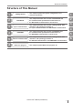
Structure of This Manual Structure of This Manual 1 Getting Started 2 EtherNet/IP 3 Cyclic communication This chapter explains the system configurations and overview of IV Series. 1 This chapter describes the overview of EtherNet/IP and the communication specifications and functions of the EtherNet/IP communication in the IV series. 2 This chapter describes the overview, setting method, data allocation, and operating procedure of the cyclic communication in the EtherNet/IP communication.
Contents Contents Introduction Symbols Cautions Safety Information for IV Series..............................1 General Precautions............................................1 Safety precautions on LED product.....................1 Important Instructions..............................................2 Precautions on use..............................................2 Measures to be taken when an abnormality occurs..................................................................
Contents Device Status Words Chapter 4 PROFINET Overview of PROFINET.......................................4-2 What is PROFINET?.........................................4-2 PROFINET communication specifications and functions in the IV series......................................4-3 IV series PROFINET communication specifications....................................................4-3 Specifying the IP address using the DCP protocol...............................................
Contents MEMO 10 - IV Series User’s Manual (Field Network) -
1 System Configuration........................................1-2 Overview of IV Series.........................................1-4 - IV Series User’s Manual (Field Network) - 1-1 1 Getting Started Getting Started This chapter explains the system configurations and overview of IV Series.
System Configuration System Configuration 1 Basic configurations of IV-Series Getting Started Connecting the host device and single sensor In addition to the status result import, the trigger control and switching of the set program number can be performed with the control output.
System Configuration 1 Connecting the host device and multiple sensors Ethernet switch Ethernet cable (2m/5m/10m) Setting support software (IV-H1) - IV Series User’s Manual (Field Network) - 1-3 Getting Started PLC or other host device In addition to the status result import, the trigger control and switching of the set program number can be performed with the control output.
Overview of IV Series Overview of IV Series 1 IV Series Getting Started The IV Series is an all-in-one “Vision Sensor” featuring a camera, a light, and a controller. This sensor can be attached easily so complicated detection operations such as detecting the shapes of parts with a photoelectric switch can be achieved easily. Operation conditions settings require the IV Software, IV-Navigator (IV-H1) or the intelligent monitor (IV‑M30).
Overview of IV Series Operation of the indicator light TRIG Green light lights up (one-shot) according to input of the internal or external trigger. yyOrange (Blink)... Flash LED has been required on the PROFINET communication I/O controller. Blinks 4 times with a period of about a second. 4 STATUS Indicates the connecting status to the PC. yyGreen (ON)....... Normally connected with monitor, PC, EtherNet/IP communication scanner, or PROFINET communication I/O controller. yyGreen (Blink).....
Overview of IV Series MEMO 1 Getting Started 1-6 - IV Series User’s Manual (Field Network) -
2 EtherNet/IP This chapter describes the overview of EtherNet/IP and the communication specifications and functions of the EtherNet/IP communication in the IV series. 2 EtherNet/IP Overview of EtherNet/IP.....................................2-2 EtherNet/IP communication specifications and functions in the IV series...........................
Overview of EtherNet/IP Overview of EtherNet/IP What is EtherNet/IP? 2 EtherNet/IP EtherNet/IP is an open industrial networking standard developed and maintained by the ODVA (Open DeviceNet Vendor Association, Inc.). All supported devices can use the communication network regardless of the vendor. Ethernet and an industrial protocol have been combined and standardized as EtherNet/IP (Industrial Protocol).
EtherNet/IP communication specifications and functions in the IV series EtherNet/IP communication specifications and functions in the IV series This section describes the overview of the EtherNet/IP communication functions supported in the IV series.
EtherNet/IP communication specifications and functions in the IV series List of supported PLCs 2 Check the instruction manual of each PLC for details of the setting methods. EtherNet/IP Keyence PLC KV series PLC model EtherNet/IP communication unit Firmware version KV-3000 KV-EP21V Ver.2 or later KV-5000 KV-EP21V Ver.2 or later KV-5500 (Built-in port or KVEP21V) Ver.2 or later Software used KV STUDIO Version of the software used Ver.6.
3 Cyclic communication This chapter describes the overview, setting method, data allocation, and operating procedure of the cyclic communication in the EtherNet/IP communication. 3 - IV Series User’s Manual (Field Network) - 3-1 Cyclic communication Overview of the cyclic communication............3-2 Cyclic communication setting method.............3-3 Data allocation in the cyclic communication....3-10 Operating procedure of the cyclic communication...............................
Overview of the cyclic communication Overview of the cyclic communication What is cyclic communication? 3 This function enables cyclic (i.e. in fixed intervals) data communications with the EtherNet/IP devices. This function provides high-speed control with several to several tens of milliseconds. The communication can be controlled by referencing and updating the variables in the PLC, making it easy to control the programs on the PLC side.
Cyclic communication setting method Cyclic communication setting method This following explains the setting method when using the cyclic communication. Network”. 3 Cyclic communication yyTo control the IV series using the EtherNet/IP communication, select [Network connection] for the sensor connection setting. When connected directly, the field network settings will be greyed out and disabled.
Cyclic communication setting method When setting by IV-Navigator (IV-H1) Set the field network settings of the sensor to [EtherNet/IP]. 3 1 Display the Advanced Sensor Settings screen. Cyclic communication 2 Select the [Environmental] tab, and then click the [Setting] button under [Field network]. 3 Select [EtherNet/IP] in [Protocol] for the field network. To enable the handshake control, check this check box .
Cyclic communication setting method PLC settings You can set the following settings for the PLC: (1) Set the connection to be used for the cyclic communication. (2) Set the device to be used for the cyclic communication. 3 For details of the setting, refer to the instruction manual of each PLC.
Cyclic communication setting method There are many types of connections, and the connection available for each device are defined in the EDS file. The following shows the list of connections that are available in the IV series.
Cyclic communication setting method Keyence KV series settings Click the connection name in the scan list. 3 The [Connection settings] screen will appear. 1 Right-click KV‑5500 in the unit editor of KV STUDIO, and then select [EtherNet/IP setting]. 2 Drag [IV Series] from the Unit list and add it to the scan list. 3 Set the Node address and IP address for the IV series on the [Initial adapter settings] screen. Connection name zz Select [Monitor/External input] or [Monitor data].
Cyclic communication setting method 6 Select [Device comment edit window] from the [Edit] menu in KV STUDIO. The [Device comment edit] screen will appear. 3 Rockwell Automation Control Logix series settings This following explains the setting method when using a Control Logix PLC. 1 Select the EtherNet/IP communication unit Cyclic communication to be connected with the IV series in the I/O configuration of RsLogix5000, and then right-click to select [New Module]. Click [Details].
Cyclic communication setting method 3 Modify the settings as necessary. yySetting the Comm Format option to [Input Data] will enable you to establish cyclic communication with multiple PLCs using the “Input only” connection. To set the Comm Format to [Input Data], perform the following settings on each PLC. Comm Format Setting contents Input Data-INT Input 100 (Assembly Instance) Name (Device name) zz You can assign a desired name.
Data allocation in the cyclic communication Data allocation in the cyclic communication Input Assembly (IV series → PLC) 3 Input Assembly are devices that write responses from the IV series to the PLC. The device map of the data allocated for the Input Assembly is as shown below. These parameters output the statuses, status results and statistics information of the IV series. For details of each parameter, refer to “Input Assembly parameter details” (Page 3-12).
Data allocation in the cyclic communication Address Bit7 Bit6 Bit5 Bit4 Bit3 Bit2 Bit1 Position correction score MAX (Unsigned 16-bit integer) 56 - 57 Position correction score MIN (Unsigned 16-bit integer) 58 - 59 Position correction score Lower threshold (Unsigned 16-bit integer) 60 - 71 Reserved by system 72 - 73 Tool 1 score (Unsigned 16-bit integer) 74 - 75 Tool 1 score MAX (Unsigned 16-bit integer) 76 - 77 Tool 1 score MIN (Unsigned 16-bit integer) 78 - 79 Tool 1 lower threshold
Data allocation in the cyclic communication Input Assembly parameter details Input Assembly Address 0: Control result (response) The Bits at Address 0 of the Input Assembly have the following functions: 3 Address Cyclic communication 0 Bit Item Content Stores the external trigger response. Data content 0 : OFF 1 : ON 0 Trigger response 1 Master image registration Stores the master image response registration response.
Data allocation in the cyclic communication Input Assembly Address 2 to 3: Handshake control/status/error result The Bits at Address 2 to 3 of the Input Assembly have the following functions: Address Bit Item Data content This bit is output when the status result can be acquired. Result update complete This bit switches the ON/OFF statuses when the status result is updated. 0 <=> 1: The statuses will be switched when the status result is updated.
Data allocation in the cyclic communication 3 Cyclic communication yyBy monitoring whether the unit is in “Imaging” status, you can determine whether the target object or the unit can be moved before completion of the image processing. yy“BUSY” and “Imaging” statuses may be skipped in some cyclic frequency settings. It is therefore necessary to take the imaging condition into consideration when setting the cyclic frequency. yyWarning statuses can be cleared from the EtherNet/IP communication.
Data allocation in the cyclic communication Input Assembly Address 4 to 7: Status result The Bits at Address 4 to 7 of the Input Assembly have the following functions: Address Bit 6 7 Data content Displays the overall status result. 0 : NG 1 : OK 1 Position correction Displays the position correction result. 0 : NG 1 : OK 2 Logic 1 Displays the result of Logic 1. 0 : NG 1 : OK 3 Logic 2 Displays the result of Logic 2. 0 : NG 1 : OK 4 Logic 3 Displays the result of Logic 3.
Data allocation in the cyclic communication Input Assembly Address 8 to 23: Error/status/status result information The Bits at Address 8 to 23 of the Input Assembly have the following functions: 3 Cyclic communication Address Data type* 8 to 9 UINT Error code Displays the currently occurring error code. 0 to 128 10 to 11 UINT Warning code Displays the currently occurring warning code.
Data allocation in the cyclic communication Input Assembly Address 24 to 51: Statistics information The Bits at Address 24 to 51 of the Input Assembly have the following functions: Address Data type* 24 to 25 UINT Processing time MAX Displays the maximum processing time value. 0 to 10000 26 to 27 UINT Processing time MIN Displays the minimum processing time value. 0 to 10000 28 to 29 UINT Processing time AVE Displays the average processing 0 to 10000 time value.
Data allocation in the cyclic communication Input Assembly Address 52 to 71: Position correction information The Bits at Address 52 to 71 of the Input Assembly have the following functions: 3 Cyclic communication Address Data type* 52 to 53 UINT Position correction tool matching rate Stores the matching rate of the position correction tool. 0 to 100 54 to 55 UINT Position correction tool matching rate MAX Stores the maximum matching rate value of the position correction tool.
Data allocation in the cyclic communication Output Assembly (PLC → IV series) Output Assembly are devices that write instructions from the PLC to the IV series. The device map of the data allocated for the Output Assembly is as shown below. These parameters are responsible for the control instructions for the IV series, clearing of warnings and handshake control. For details of each parameter, refer to “Output Assembly parameter details” (Page 3-20).
Data allocation in the cyclic communication Output Assembly parameter details Output Assembly Address 0 to 1: Control request The Bits at Address 0 to 1 of the Output Assembly have the following functions: 3 Address Cyclic communication 0 1 Bit Item Content Requests the external trigger. Data content 0 Trigger request 0 : OFF 1 : ON 1 Master image registration Requests a master image request registration. 0 : OFF 1 : ON 2 Program switching request Requests a program switching.
Data allocation in the cyclic communication Output Assembly Address 2 to 3: Handshake control The Bits at Address 2 to 3 of the Output Assembly have the following functions: Address 2 Item Content Data content 0 Result acquisition complete notification Permits the updating of the status result. 0: OFF 1: ON 1 to 7 Reserved by system --- --- 0 to 7 Reserved by system --- --- 3 A result acquisition completion notice is used when handshake control is [Enabled].
Data allocation in the cyclic communication Error code list The following shows the list of error codes that are generated in the IV series. 3 Error code 0 Cyclic communication 1 - 32 Content Countermeasure No error --- --- Program No. xx corruption error yyA data error has occurred in program No. xx. yyThe data corruption may have occurred due to a power-off while writing settings data and/or due to noise. yyInitialize the program No. xx. yySwitch on the power back ON.
Data allocation in the cyclic communication Warning code list The following shows the list of warning codes that are generated in the IV series. Warning code Content Cause Countermeasure 3 No error --- --- 62 Field network overrun error An overrun of the status result has occurred. Request a result acquisition completion notice to permit the updating of the status result.
Data allocation in the cyclic communication Warning code 3 Content Cyclic communication Cause Countermeasure 70 FTP Transfer Error (Insufficient Data Buffer) The transfer has failed because a volume of data exceeding the remaining FTP buffer capacity has been generated. yyModify the trigger cycle of this unit. yyCheck the load status of the network. 71 FTP Transfer Error (Transfer Failed) The data transfer to the destination folder has failed.
Data allocation in the cyclic communication MEMO 3 Cyclic communication - IV Series User’s Manual (Field Network) - 3-25
Operating procedure of the cyclic communication Operating procedure of the cyclic communication This section explains the method for communicating from the PLC to the IV series using cyclic communication. Reading out the overall status result of the IV series (Handshake control [Disabled]) 3 When a trigger is successful Cyclic communication Trigger request A B Trigger response A B BUSY A B Imaging status A B Result update complete A B Result available Result No.
Operating procedure of the cyclic communication When a trigger is unsuccessful Trigger request Trigger response A B A Trigger failed C B C B C A C Imaging status A C Result update complete A Cyclic communication BUSY 3 C Result available Result No. Overall judgment A Result of A C Result of C Warning Warning No. Warning No. (1) (2) (3) (4) Execute a [Trigger request]. (0 → 1) If the trigger is valid, [Trigger response] will change from 0 to 1.
Operating procedure of the cyclic communication Reading out the overall status result of the IV series (Handshake control [Enabled]) 3 The following describes the operating procedure when the data handshake control is set to [Enabled]. You can acquire all status results without fail by setting the data handshake control to [Enabled].
Operating procedure of the cyclic communication Switching the programs in the IV series Program No. Program No. Program switching request 3 Program switching response Cyclic communication BUSY (1) Write the program No. to be set to [Program No.]. For the write range setting, refer to “Output Assembly parameter details” (Page 3-20). (2) Execute [Program switching request]. (0 → 1) (3) You can check the input status in [Program switching response].
Operating procedure of the cyclic communication Registering a master image for the IV series externally Master registration request 3 Master registration response BUSY Cyclic communication (1) Execute a [Master registration request]. (0 → 1) (2) You can check the input status in [Master registration response]. yy[BUSY] will change from 0 to 1 while the master image registration is in progress. yyIf the master image registration is unsuccessful, [Master registration failed] will change from 0 to 1.
4 PROFINET This chapter describes the overview of PROFINET and the communication specifications and functions of the PROFINET communication in the IV series. - IV Series User’s Manual (Field Network) - 4-1 4 PROFINET Overview of PROFINET......................................4-2 PROFINET communication specifications and functions in the IV series...........................
Overview of PROFINET Overview of PROFINET What is PROFINET? PROFINET is an open industrial networking standard developed and maintained by the PI (PROFINET International). All supported devices can use the communication network regardless of the vendor. PROFINET allows easy integration with the currently used field bus (such as PROFIBUS), enabling you to protect the existing assets without modifying the legacy system.
PROFINET communication specifications and functions in the IV series PROFINET communication specifications and functions in the IV series IV series PROFINET communication specifications Data I/O communication Communication size to 408 byte Specifying the IP address using the DCP protocol In the PROFINET communication, you can specify the IP address of I/O devices using the DCP protocol (Discovery and Configuration Protocol). PROFINET The DCP protocol offers two methods for setting the IP address.
PROFINET communication specifications and functions in the IV series Overview of the PROFINET communication functions in the IV series The following shows the list of functions that can be used to control the IV series in the PROFINET communication. Function 4 Content PROFINET Trigger input Executes a trigger input for the sensor. Program switching Executes a program switching for the sensor. External master registration Executes an external master registration for the sensor.
PROFINET communication specifications and functions in the IV series List of supported PLCs Check the instruction manual of each PLC for details of the setting methods. Siemens PLC PROFINET communication unit PLC model Firmware version Software used Version of the software used V2.6 or later STEP 7 V5.5.0.0 or later S7 400 series Example: CPU414-3 PN/DP (Built in the unit) V5.3 or later STEP 7 V5.5.0.0 or later S7 1200 series Example: CPU1212C V2.
PROFINET communication specifications and functions in the IV series MEMO 4 PROFINET 4-6 - IV Series User’s Manual (Field Network) -
5 Data I/O communication This chapter describes the overview, setting method, data allocation, and operating procedure of the data I/O communication in the PROFINET communication. - IV Series User’s Manual (Field Network) - 5-1 5 Data I/O communication Overview of the data I/O communication.........5-2 Data I/O communication setting method..........5-3 Data allocations in the data I/O communication............................5-16 Operating procedure of the data I/O communication.....................
Overview of the data I/O communication Overview of the data I/O communication What is data I/O communication? This function enables cyclic (i.e. in fixed intervals) data communications with the PROFINET devices. This function provides high-speed control with several to several tens of milliseconds. The communication can be controlled by referencing and updating the variables in the PLC, making it easy to control the programs on the PLC side.
Data I/O communication setting method Data I/O communication setting method This following explains the setting method when using the data I/O communication. network. 5 4 Select [PROFINET] for the protocol. Setting the IV series You can configure the following settings for the IV series using the monitor (IV-M30) or IV-Navigator (IV-H1). When settings on the monitor (IV-M30) Set the field network settings of the sensor to [PROFINET].
Data I/O communication setting method When setting by IV-Navigator (IV-H1) Set the field network settings of the sensor to [PROFINET]. 5 Click the [OK] button. You will return to the main screen of [Setting]. 1 Open the sensor expansion settings screen. 2 Select the [Device settings] tab, and then click the [Settings] button under [Field network]. 5 Data I/O communication 3 Select [PROFINET] in [Protocol] for the field network. Tick the checkbox if you wish to enable the data handshake control.
Data I/O communication setting method Setting the device name When setting by IV-Navigator (IV-H1) When settings on the monitor (IV-M30) 1 Touch the [Sensor expansion settings] button on the sensor settings menu screen. 2 Touch the [Environment setting] button, 1 Open the sensor expansion settings screen. 2 Select the [Device settings] tab. 3 Set the environment settings of the sensor. 5 Device name zz Displays the name of the sensor.
Data I/O communication setting method PLC settings You can set the following settings for the PLC: (1) Establish a real-time communication for setting up the data I/O communication. (2) Se the I/O device to be used for the data I/O communication. For details of the setting, Refer to the instruction manual of each PLC.
Data I/O communication setting method Setting the Siemens TIA Portal This following explains the setting method when using TIA Portal. 4 Right-click the selected CPU in [Project tree], and then click [Open]. 1 Launch [TIA Portal V11] with the PC and CPU connected. 5 Data I/O communication 2 Select the [Device & Networks] tab, and then click [Add new device]. The [(Set device name [Selected CPU])] screen will appear. The [Add new device] screen will appear. 3 Select the CPU to be connected.
Data I/O communication setting method 6 Install the GSDML file if you are configuring the IV series for the first time. 5 Data I/O communication yySelect [Install general station description file (GSD)] from the [OptIOns] menu. yySelect the GSDML file for the IV series you wish to install, and then click the [Install] button. yyRestart TIA Portal V11 after the installation. The GSDML file for the IV series can be downloaded from the KEYENCE web site. http: //www.keyence.co.
Data I/O communication setting method 11 Click the [Properties] tab. Select [PROFINET interface [x1]] - [Ethernet addresses] under [General], and then select the IP address setting method for the IV series. To set a new IP address for the IV series zz 12 Click the [Properties] tab. Select [PROFINET interface [x1]] - [Advanced options] - [Real time settings] in [General], and then set the SendCycle (communication cycle) for the data I/O communication in [Update time].
Data I/O communication setting method 14 Click the CPU in the [Devices] tab. Select [Download to device] - [All] to download the setting to the CPU. 16 Set the CPU mode switch to “RUN”. If the connection is successful, the RUN LED of the CPU will light in green and the data I/O communication will become enabled. yyBy default, [Size of the process-image input area] is set to “128”. To be able to access the addresses after address 128, expand the setting as shown below.
Data I/O communication setting method Setting the Siemens SIMATIC Manager This following explains the setting method when using SIMATIC Manager. 4 Expand [Object Hierarchy] and select [SIMATIC 300], and then double-click [Hardware]. 1 Launch [SIMATIC Manager] with the PC and CPU connected, and then select [New] from the [File] menu. 2 Enter the project name into the [Name] field, and then click the [OK] button. 5 The [HW Config] window will appear.
Data I/O communication setting method 7 Set the IP address and subnet mask of the 10 Install the GSDML file if you are CPU, and then click the [New] button. 5 Data I/O communication The [Properties-New subnet Industrial Ethernet] window will appear. 8 Click the [OK] button to return to the [Properties-Ethernet interface PN-IO] window. configuring the IV series for the first time. yySelect [Options] - [Install GSD File] in the [HW Config] window.
Data I/O communication setting method 11 Open [PROFINET IO] - [Additional Field Devices] - [Sensors] - [Keyence Vision Sensors] from [Hardware Catalog] in the [HW Config] window, and then drag & drop [IV-xxxx] onto [PROFINET-IO-System] in the Station Window. 12 Double-click the IV series icon in the [HW Config] window. The [Properties - IV series] window will appear. 13 Enter the same character string as the PROFINET device name of the IV series to be connected into the [Device name] field.
Data I/O communication setting method 17 Select [Station] - [Save and Compile] in the [HW Config] window, and save the settings. 18 Select [PLC] - [Download] in the [HW Config] window to download the settings to the CPU. 19 Set the CPU mode switch to “RUN”. 5 If the connection is successful, the RUN LED of the CPU will light in green and the data I/O communication will become enabled. Data I/O communication yyBy default, [Size of the process-image input area] is set to “128”.
Data I/O communication setting method MEMO 5 Data I/O communication - IV Series User’s Manual (Field Network) - 5-15
Data allocations in the data I/O communication Data allocations in the data I/O communication The PROFINET communication for the IV series is defined using the following modules: yyCommand Control Module yyCommand Status Bits Module yyDevice Result Bits Module yyDevice Status Words Module yyDevice Statistics Module yyPosition Adjust Result Module yyTool Result Module 5 Control Modules (PLC → IV series) Data I/O communication Control Modules are modules that write instructions from the PLC to the IV ser
Data allocations in the data I/O communication Status Modules (IV series → PLC) Status Modules are modules that write responses from the IV series to the PLC. The device map of the data allocated for the Status Modules is as shown below. These parameters output the statuses, status results and statistics information of the IV series. For details of each parameter, refer to “Status Modules parameter details” (Page 5-22). Command Status Bits Slot No.
Data allocations in the data I/O communication Device Status Words Slot No.: 4 Module size: 16 bytes Address 5 Bit7 Bit6 Bit5 Bit4 Bit3 Bit2 Data I/O communication 0-1 Error No. (Unsigned 16-bit data) 2-3 Warning No. (Unsigned 16-bit data) 4-5 Number of remaining buffers (Unsigned 16-bit data) 6-7 Checksum (Unsigned 16-bit data) 8-9 Current program No. (Unsigned 16-bit data) 10 - 11 Program No. during judgment (Unsigned 16-bit data) 12 - 13 Result No.
Data allocations in the data I/O communication Tool Result Modules (IV series→ PLC) Tool Result Modules are modules that write responses from the IV series to the PLC. The device map of the data allocated for the Tool Result Modules is as shown below. Stores the matching rate and threshold information of the position correction and other tools. For details of each parameter, refer to “Tool Result Modules parameter details” (Page 5-28). Position Adjust Result Slot No.
Data allocations in the data I/O communication Control Modules parameter details Command Control Address 0 to 1: Control request The Bits at Address 0 to 1 of the Command Control have the following functions: Address 5 Data I/O communication 0 1 Bit Item Content Requests the external trigger. Data content 0 : OFF 1 : ON 0 Trigger request 1 Master image registration Requests a master image request registration. 0 : OFF 1 : ON 2 Program switching request Requests a program switching.
Data allocations in the data I/O communication Command Control Address 2 to 3: Handshake control The Bits at Address 2 to 3 of the Command Control have the following functions: Address 2 3 Bit Item Content Data content 0 Result acquisition complete notification Permits the updating of the status result. 0 : OFF 1 : ON 1 to 7 Reserved by system --- --- 0 to 7 Reserved by system --- --- Command Control Address 4 to 11: Program No.
Data allocations in the data I/O communication Status Modules parameter details Command Status Bits Address 0: Control result (response) The Bits at Address 0 of the Command Status Bits have the following functions: Address 5 Data I/O communication 0 Bit Item Content Stores the external trigger response. Data content 0 : OFF 1 : ON 0 Trigger response 1 Master image registration Stores the master image response registration response.
Data allocations in the data I/O communication Command Status Bits Address 2 to 3: Handshake control/status/error result The Bits at Address 2 to 3 of the Command Status Bits have the following functions: Address Bit Item Data content Result available This bit is output when the status result can be acquired. 0 : The status result cannot be acquired. 1 : The status result can be acquired. Result update complete This bit switches the ON/OFF statuses when the status result is updated.
Data allocations in the data I/O communication yyBy monitoring whether the unit is in “Imaging” status, you can determine whether the target object or the unit can be moved before completion of the image processing. yy“BUSY” and “Imaging” statuses may be skipped in some data I/O cycle settings. It is therefore necessary to take the imaging condition into consideration when setting the cyclic frequency. yyWarning statuses can be cleared from the PROFINET communication.
Data allocations in the data I/O communication Device Results Bits Address 0 to 3: Status result The Bits at Address 0 to 3 of the Device Results Bits have the following functions: Address 0 2 3 Item Content Data content 0 Overall judgment Displays the overall status result. 0 : NG 1 : OK 1 Position correction Displays the position correction result. 0 : NG 1 : OK 2 Logic 1 Displays the result of Logic 1. 0 : NG 1 : OK 3 Logic 2 Displays the result of Logic 2.
Data allocations in the data I/O communication Device Status Words Address 0 to 15: Error/status/status result information The Bits at Address 0 to 15 of the Device Status Words have the following functions: 5 Data I/O communication Address Data type* 0 to 1 WORD Error code Displays the currently occurring error code. 0 to 128 2 to 3 WORD Warning code Displays the currently occurring warning code.
Data allocations in the data I/O communication Device Statistics Address 0 to 27 (Statistics information) The Bits at Address 0 to 27 of the Device Statistics have the following functions: Address Data type* 0 to 1 WORD Processing time MAX Displays the maximum processing time value. 0 to 10000 2 to 3 WORD Processing time MIN Displays the minimum processing time value. 0 to 10000 4 to 5 WORD Processing time AVE Displays the average processing 0 to 10000 time value.
Data allocations in the data I/O communication Tool Result Modules parameter details Position Adjust Result Address 0 to 19 (Position correction information) The Bits at Address 0 to 19 of the Position Adjust Result have the following functions: 5 Data I/O communication Address Data type* 0 to 1 WORD Position correction tool matching rate 2 to 3 WORD Position correction tool Matching rate MAX 4 to 5 WORD Position correction tool Matching rate MIN 6 to 7 WORD 8 to 19 --- * WORD : DWORD
Data allocations in the data I/O communication Error code list The following shows the list of error codes that are generated in the IV series. Error code 0 1 - 32 Content Countermeasure --- --- Program No. xx corruption error yyA data error has occurred in program No. xx. yyThe data corruption may have occurred due to a power-off while writing settings data and/or due to noise. yyInitialize the program No. xx. yySwitch on the power back ON.
Data allocations in the data I/O communication Warning code list The following shows the list of warning codes that are generated in the IV series. Warning code 5 Content Cause Countermeasure Data I/O communication 0 No error --- --- 62 Field network overrun error An overrun of the status result has occurred. Request a result acquisition completion notice to permit the updating of the status result.
Data allocations in the data I/O communication Warning code Content Cause Countermeasure 70 FTP Transfer Error (Insufficient Data Buffer) The transfer has failed because a volume of data exceeding the remaining FTP buffer capacity has been generated. yyModify the trigger cycle of this unit. yyCheck the load status of the network. 71 FTP Transfer Error (Transfer Failed) The data transfer to the Check the access permissions of the destination folder has failed. destination folder.
Operating procedure of the data I/O communication Operating procedure of the data I/O communication This section explains the method for communicating from the PLC to the IV series using data I/O communication. Reading out the overall status result of the IV series (Handshake control [Disabled]) When a trigger is successful Trigger request 5 A B Data I/O communication Trigger response A B BUSY A B Imaging status A B Result update complete A B Result available Result No.
Operating procedure of the data I/O communication When a trigger is unsuccessful Trigger request Trigger response A B A Trigger failed C B C B C BUSY A C Imaging status A C Result update complete A C 5 Result available Overall judgment A Result of A C Result of C Warning Warning No. Warning No. (1) Execute a [Trigger request]. (0 → 1) (2) If the trigger is valid, the [Trigger response] will change from 0 to 1. (3) [BUSY] will change from 0 to 1 when a trigger is input.
Operating procedure of the data I/O communication Reading out the overall status result of the IV series (Handshake control [Enabled]) The following describes the operating procedure when the data handshake control is set to [Enabled]. You can acquire all status results without fail by setting the data handshake control to [Enabled].
Operating procedure of the data I/O communication Switching the programs in the IV series Program No. Program No. Program switching request Program switching response BUSY (1) Write the program No. to be set to [Program No.]. For the write range setting, refer to “Control Modules parameter details” (Page 5-20). (2) Execute [Program switching request]. (0 → 1) (3) You can check the input status in [Program switching response].
Operating procedure of the data I/O communication Registering a master image for the IV series externally Master registration request Master registration response BUSY (1) Execute a [Master registration request]. (0 → 1) (2) You can check the input status in [Master registration response]. 5 Data I/O communication yy[BUSY] will change from 0 to 1 while the master image registration is in progress. yyIf the master image registration is unsuccessful, [Master registration failed] will change from 0 to 1.
Appendices Reference program (EtherNet/IP)..................... A-2 Reference program (PROFINET)...................... A-8 Index.................................................................
Reference program (EtherNet/IP) Reference program (EtherNet/IP) This section introduces a reference program for when using EtherNet/IP communication in the IV series. In the actual operation, programming must be performed taking the error processing, etc. into consideration.
Reference program (EtherNet/IP) Rockwell Automation PLC Trigger Ack REQ Trigger ONS Rung0 Trigger Result Ready Complete Toggle ONS Rung1 MOV Move Source Dest Tool Score Result A Complete Toggle ONS Description of the reference program Rung0 zz Sets “REQ” to ON and executes “Trigger”. “Trigger Ack” ON will set Trigger to OFF (“Trigger” will be retained until “Trigger Ack” becomes ON).
Reference program (EtherNet/IP) Handshake control [Enabled] Keyence KV series REQ Trigger response Trigger request Line 1 Trigger request Line 2 MOV Result available A Tool score Line 3 Result available Result available DM2000 Result acquisition complete notification Line 4 Result acquisition complete notification Line 5 Description of the reference program Line 1/Line 2 zz Sets “REQ” to ON and executes a trigger request.
Reference program (EtherNet/IP) Rockwell Automation PLC Trigger Ack REQ Trigger ONS Rung0 Trigger MOV Move Source Dest Result Ready ONS Rung1 Result Ready Result Ready Tool Score Result A Result Ready Ack ONS Rung2 Result Ready Ack Description of the reference program Rung0 zz Sets “REQ” to ON and executes “Trigger”. “Trigger Ack” ON will set Trigger to OFF (“Trigger” will be retained until “Trigger Ack” becomes ON).
Reference program (EtherNet/IP) Program switching Keyence KV series REQ MOV DM1000 Line 1 Program switching response REQ Program No. Program switching request Line 2 Program switching request A Line 3 Description of the reference program Line 1 zz This line sets “REQ” to ON and copies the DM1000 data, which contains the program No. to be set, to the program No. Line 2/Line 3 zz Sets “REQ” to ON and executes a program switching request.
Reference program (EtherNet/IP) Rockwell Automation PLC MOV Move Source Dest REQ ONS Rung0 REQ Program Change Ack Number Program Number Program Change ONS Rung1 Program Change A Description of the reference program Rung0 zz This line sets “REQ” to ON and copies the Number data, which contains the program No. to be set, to the program No. Rung1 zz Sets “REQ” to ON and executes “Program Change”.
Reference program (PROFINET) Reference program (PROFINET) This section introduces a reference program for when using the PROFINET communication in the IV series. In the actual operation, programming must be performed taking the error processing, etc. into consideration.
Reference program (PROFINET) Handshake control [Enabled] Siemens PLC Network1 REQ P Trigger Ack Trigger Trigger Network2 MOV Result Ready P EN Tool Score Network3 Result Ready P Result Ready IN A ENO OUT Result Result Ready Ack Result Ready Ack Description of the reference program Network1 zz Sets “REQ” to ON and executes “Trigger”. “Trigger Ack” ON will set “Trigger” to OFF (“Trigger” will be retained until “Trigger Ack” becomes ON).
Reference program (PROFINET) Program switching Siemens PLC Network1 MOV REQ P EN Number A Network2 REQ P IN Program Change Ack ENO OUT Program Number Program Change Program Change Description of the reference program Network1 zz This line sets “REQ” to ON and copies the Number data, which contains the program No. to be set, to the program No. Network2 zz Sets “REQ” to ON and executes “Program Change”.
Reference program (PROFINET) MEMO A - IV Series User’s Manual (Field Network) - A-11
Index Index B O Basic configurations of IV-Series..........................1-2 C Connecting the host device and multiple sensors...................................................1-3 Connecting the host device and single sensor.....1-2 Control Modules parameter details....................5-20 Control Modules (PLC → IV series)...................5-16 Cyclic communication...........................................3-2 Cyclic communication setting method..................
Index T Tool Result Modules (IV series→ PLC)..............5-19 W Warning code list...................................... 3-23, 5-30 What is cyclic communication?............................3-2 What is data I/O communication?........................5-2 What is EtherNet/IP?............................................2-2 What is PROFINET?............................................
Revision history Revision history Edition number December, 2012 1st edition December, 2013 2nd edition April, 2014 3rd edition Revision details Ethernet and Monitor cable changed
WARRANTIES AND DISCLAIMERS (1) KEYENCE warrants the Products to be free of defects in materials and workmanship for a period of one (1) year from the date of shipment. If any models or samples were shown to Buyer, such models or samples were used merely to illustrate the general type and quality of the Products and not to represent that the Products would necessarily conform to said models or samples.
2012 244008E 1044-3 256GB