
User Manual

8
GT2-70-M-E
2
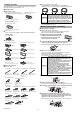
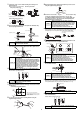
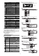
Detect the good workpiece and press the [SET] button to capture the
detected value.
"SEt" and the detected value blink alternately, and the value of the
good workpiece is fixed.
3
Detect the HIGH defective workpiece and press the [SET] button to
capture the detected value.
The median value of this detected value and the one captured in step 2 blinks.
HIGH setting value is fixed.
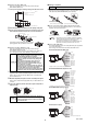
4
Press the right Arrow button until the LOW
setting value display of the main display
appears.
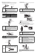
5
Detect the good workpiece again and press the
[SET] button to capture the detected value.
6
Detect the LOW defective workpiece and press the [SET] button to
capture the detected value.
The median value of this detected value
and the one captured in step 5 blinks.
LOW setting value is fixed.
Two-point tuning is completed.
Press the left/right Arrow buttons to
return to the P.V. value display.
■
Preset
This function displays the value obtained by adding or subtracting a
preset value to or from the detected value.
By using this function and the zero point correction function together,
you can set an arbitrary value as a reference point of the work.
Refer to "Preset Function" in the "GT2-70 Series User's Manual" for
details about the preset function.
■
Bank switching
By using the bank function, the setting values of the HH side, HIGH
side, LOW side, LL side, preset point, and the preset value can be
registered up to four patterns.
The bank switching is useful when there are multiple detection targets
since the pre-registered settings (four patterns) can be easily switched.
Refer to "Bank Function" in the "GT2-70 Series User's Manual" for
details about the bank function.
■
Limit output function
This function can detect and output the mechanical movement of the spindle
on the contraction and extension sides. The stroke end of both sides can be
detected, so this function can be used for interlocking the device.
■
5-output
This function can increase the output levels to 5 levels: HH, HIGH,
GO, LOW, and LL. HH/LL can be set in the same way as HIGH/LOW.
Refer to "Setting 5-output" in the "GT2-70 Series User's Manual" for
details about the 5-output function.
■
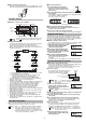
Analog output function
On GT2-71MCN/71MCP, the analog current (4 to 20 mA) is output
based on the measurement value (R.V.). The upper limit value and
the lower limit value can be set to a desired value.
Refer to "Analog Output Settings" in the "GT2-70 Series User's
Manual" for details about the analog output function.
■
Calculation with expansion unit
The GT2-70 Series can calculate various values using the detected
values of multiple detection points such as the maximum value or the
minimum value when an expansion unit(s) is added (up to 14 units).
Refer to pages 2 to 3 of this manual for details about how to add an
expansion unit.
The outline of the calculation function is shown below.
●
Calculation mode
When "Calculation mode" is selected in "A1. Calculation mode", the main unit
outputs the calculation result, while the expansion unit does not. Only the head
indicator operates in the same way as the one on the main unit. (Except when
"C5. Reference difference" is selected for the calculation method)
Refer to "Calculation with expansion unit" in the "GT2-70 Series User's Manual"
for details about the calculation function.
●
Calculation only mode
When calculation only mode is selected in [A1. Calculation mode],
only the main unit outputs the calculation result, and the expansion
unit outputs the judgment according to each setting.
Refer to "Calculation with expansion unit" in the "GT2-70 Series
User's Manual" for details about calculation only mode.
■
Keylock
The keylock allows you to avoid erroneous button operation during detection.
When the keylock is active, setup operations other than changing the display are disabled.
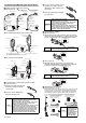
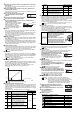
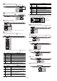
●
Set the keylock
When keylock is active, setup operations other than main display
switching and the [PRESET] button operation are disabled.
When in the main display, while pressing
the [MODE] button, press the upper Arrow
button for at least two seconds.
The keylock display will appear for several
seconds and then change to the main display.
+ (Press for at least two seconds)
●
Set full keylock
When full keylock is active, setup operations other than main display
switching are disabled.
Press the down Arrow button for at least two
seconds while pressing the [MODE] button in
the main display.
+ (Press for at least two seconds)
●
Cancel the keylock or full keylock
Press "up or down" Arrow button for at least
two seconds while pressing the [MODE] button
in the main display when the keylock is active.
The keylock cancel display will appear for several
seconds and then change to the main display.
+ or (Press for at least two seconds)
■
Initialize (Reset to the default state)
1
When in the main display, while pressing the
[MODE] button, press the [SET] button five times.
"rSt.no" will appear.
2
Press the top/bottom Arrow buttons to select "rSt.YES".
3
Press the [MODE] button.
"rSt.End" will appear.
Initialization is completed.
●
Default value list
Default values of function settings
Reference
The limit output function cannot be used on GT2-71MCN/
71MCP (analog output type).
Reference
The 5-output function cannot be used on GT2-71MCN/
71MCP (analog output type).
Reference
The analog output function can only be used on GT2-
71MCN/71MCP (analog output type).
No.
Calculation
function
Description
Number of units connected
Calculation
mode
Calculation
only mode
C1
Max.
value
Displays the maximum value of the values
of the main unit and expansion unit(s)
1 to 14 units
2 to 14 units
C2
Min.
value
Displays the minimum value of the values
of the main unit and expansion unit(s)
C3
Flatness
Displays a difference between the maximum
value and the minimum value of the values
of the main unit and expansion unit(s)
C4
Average
Displays the average obtained by dividing the
sum of the values of the main unit and expansion
unit(s) by the number of units connected
C5
Reference
difference
Displays a difference obtained by
subtracting the display value of the main
unit from that of each expansion unit(s)
Not selectable
LOW setting value display
HIGH
setting value
LOW
setting value
HIGH defective
workpiece
Good
workpiece
LOW defective
workpiece
Current output
Measurement value
Upper limit valueLower limit value
0
20mA
4mA
C6 Twist
Displays a degree of twist obtained from
the values of four detection points
3 units only 4 units only
C7
Warpage
Displays a degree of warpage obtained
from the values of three detection points
2 units only 3 units only
C8
Thickness
Displays a thickness obtained by
sandwiching the detection target between
the main unit and the expansion unit
1 unit only 2 units only
Reference
The calculation mode can be selected only on the main unit
with one or more expansion units connected.
NOTICE
• The calculation only mode is available only on the main
unit with two or more expansion units connected.
• When the calculation only mode is
selected, "C5. Reference difference"
cannot be selected for the
calculation method.
• When the calculation only mode is
selected, the sensor head cannot be
connected to the main unit. Attach
the included "head connector label"
to the head connector of the main unit.
Reference
The keylock can be set on the main display only.
Reference
• Initialization can be set on the main display only.
• Initialization cannot cancel "span adjustment results".
• Refer to "Calibration" in the "GT2-70 Series User's Manual" for details
about how to set "Span adjustment" to the factory default state.
• During initialization, performing other steps than the following ones
stops initialization, and the display returns to the main display.
Setting item Initial value
Detection mode
Std
Hold update method
tim
Response time
100 (400)*
1
Timing type
t-in
Self timing level
0.5000
Self timing delay type
Stb.d
User specified delay time
t=1000
No.
Calculation
function
Description
Number of units connected
Calculation
mode
Calculation
only mode
Keylock display
MOD
E
Full keylock display
MOD
E
Keylock cancel display
MOD
E