
User Manual

7
GT2-70-M-E
■
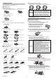
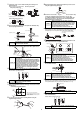
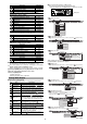
How to mount the lift lever
Mount the lift lever (OP-84397) between the spindle and the contact.
Secure the spindle with the lift lever and attach/detach the contact.
Amplifier display
■
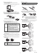
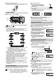
Names of parts of the amplifier
■
Digital LED display
The main display during detection can be switched to the displays
as shown below by pressing the left/right Arrow buttons.
Refer to "Detection Functions" in the "GT2-70 Series User's
Manual" for details about the setting mode screen in which various
settings are performed.
*1 This display appears only while the calculation function is used
and an expansion unit is connected.
*2 • This display appears only when [5out] is selected for [16.
Special output setting] in the basic setting mode.
• This display does not appear on GT2-71MCN/71MCP.
1. P.V. value display ([P.V. = Present Value] Criterion value display)
Displays a value to be used for output judgment.
2. Calculated value display
Displays a calculated value such as a maximum or minimum value
of several detection points created when adding an expansion
unit(s) (Displayed only when an expansion unit(s) is added).
3. R.V. value display ([R.V. = Raw Value] Raw value display)
Displays an actual detection value of the detection target.
4. HH setting value display while using 5-output function
Displays/Sets the setting value to set above the HIGH setting value.
5. HIGH setting value display
Displays/Sets an upper limit value of the range of the detection target.
6. LOW setting value display
Displays/Sets a lower limit value of the
range
of the detection target.
7. LL setting value display while using 5-output function
Displays/Sets the setting value to set below the LOW setting value.
8. Preset value setup display
Displays/Sets an arbitrary value to be added to or subtracted from
the display value.
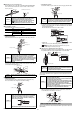
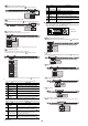
Zero-Point Correction
When you use this equipment for the first time or after the sensor head
is changed, be sure to correct the reference zero point.
■
Setup using buttons
1
Set any main display and perform the
detection of the detection target (master
workpiece) to serve as a reference for zero-
point correction.
2
Press the [PRESET] button (white button) with the master workpiece
being detected.
After "PrESEt" has blinked several times on the digital LED display
of the amplifier, "0.000.0"* will appear.
The zero-correction is completed.
* When the preset function is set, the preset value will appear.
■
Setup using external input (Pink wire)
1
Perform detection of the target (master workpiece) to serve as a
reference for zero-point correction.
2
Connect the pink wire to the appropriate terminal.
Refer to page 15 of this manual for details about external input circuit diagrams.
Setup of Limit Values
The limit values are an upper limit value (HIGH setting value) and a
lower limit value (LOW setting value). Setting these values enables
three types of judgment (display/output): above the upper limit (HIGH),
below the lower limit (LOW), and within the range (GO).
■
Manual setup of limit values
The following shows how to set manually an upper limit value (HIGH
setting value) and a lower limit value (LOW setting value).
1
When in the main display, press the left/
right Arrow buttons until the HIGH
setting value display appears.
2
Enter an upper limit value (HIGH setting
value) with the top/bottom Arrow buttons.
3
Press the right Arrow button to display the
LOW setting value display.
4
Enter a lower limit value (LOW setting
value) with the top/bottom Arrow buttons.
The setup of range criteria values is
completed.
To return to the P.V. value display, press the left/right Arrow buttons.
Tips for Convenient Functions
■
Automatic setup of limit values
This function automatically sets an upper limit value (HIGH setting
value) and a lower limit value (LOW setting value).
For master workpieces, set by "tolerance tuning"; and for actual
works (good or defective), set by "two-point tuning".
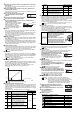
●
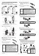
Tolerance tuning
1
When in the main display, press the left/
right Arrow buttons until the P.V. value
display appears, then perform detection of
the master workpiece.
2
Press the [SET] button while the master workpiece is being detected
to capture the detected value.
3
Press the upper/bottom Arrow buttons to enter a tolerance tuning
setting range.
4
Press the [SET] button to fix the tolerance tuning setting range.
After [SEt] blinks several times on the digital LED display of the
amplifier, the P.V. value display automatically appears.
Tolerance tuning is completed.
●
Two-point tuning
This is the method of setting the median values of the detected
good and/or defective workpieces as a range when the good
workpiece and HIGH/LOW defective workpieces are available.
1
When in the main display, press the left/
right Arrow buttons until the HIGH setting
value display appears.
Reference
For details about the GT2-71D (pulse output type) amplifier,
refer to "
GT2-71D (pulse output type)
" (page 13).
Reference
• When "------" is displayed, zero-point correction is disabled.
• Zero-point correction can be performed approx. 1 million
times. When zero-point calibration is frequently used, you
can perform setting so that the zero-point calibration will not
be written into the memory. Refer to "Origin Alignment" in the
"GT2-70 Series User's Manual" for details.
GT2-71
GT2-71
Detection level
indicator
[PRESET]
button
Status indicator Arrow buttons
PV indicator
Preset indicator
HIGH position indicator/
LOW position indicator
Digital LED display
[MODE] button
Bar LEDs
Bank indicator [SET] button
Special output indicator
Timing input
indicator
1. P.V. value display
2. Calculated value display*
1
3. R.V. value display
8. Preset value setup display
7. LL setting value display
while using 5-output function*
2
4. HH setting value display
while using 5-output function*
2
6. LOW setting value display
5. HIGH setting value display
Reference
When "------" is displayed, tolerance tuning is disabled.
When "-FFFF" or "FFFF" is displayed, the settings cannot
be set correctly.
Reference
Tolerance tuning is enabled only when in the P.V. value
display.
Reference
Two-point tuning is disabled when "------" is displayed as a
R.V. value. When "- FFFF" or "FFFF" is displayed, setting
cannot be done accurately.
Master workpiece
HIGH setting value display
LOW setting value display
HIGH setting value
LOW setting value
Tolerance tuning setting range
This is a method for setting a range based on
the detection value of a master workpiece
when the master workpiece is available.
HIGH setting value display