
User Manual

5
GT2-70-M-E
1
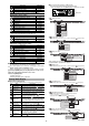
Cut the jig to create a sensor head mounting hole referring to the
illustration below.
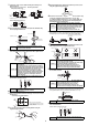
2
Insert the tightening sleeve into the hole (from the Chamfered side),
and loosely tighten with the nut.
3
Insert the sensor head in the tightening sleeve. While securing the tightening
sleeve with the included key wrench, tighten the nut with a separate wrench.
4
Rotate the dust boot so that the side line is straight. (Models other
than GT2-PA12K/PA12)
Check with the spindle pushed in.
●
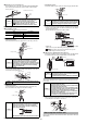
Using mounting bracket F
1
Refer to the illustration below and cut the jig to create a sensor head
mounting hole.
2
Loosen the screw on the side of mounting bracket F using the
supplied hexagonal wrench.
3
Align mounting bracket F with the hole made in step 1 and secure it
using the supplied hexagonal wrench.
4
Insert the sensor head, and tighten the screw loosened in step
2 using the supplied hexagonal wrench to secure. The
recommended tightening torque is 0.6 to 0.8 N•m. Make sure
that the dust boot does not obstruct the metal plating that
mounting bracket F is attached to.
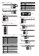
●
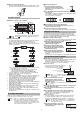
Mounting on the side of a surface
When mounting to the side of a GT2-P12K(L)/P12(L)/PA12K/PA12/H12K(L)/H12(L)/
A12K(L)/A12(L) unit, use the optional head mounting bracket B (OP-76875).
1
Insert the tightening sleeve into the mounting bracket from the side
with a depression, and loosely tighten with the nut.
2
Insert the sensor head into the tightening sleeve, and tighten
the nut with a wrench.
3
Secure the sensor head with M4 screws.
Mount the sensor head with the model label on top. For GT2-P12K (L)/
P12 (L)/PA12K /PA12, mount so that the head indicator is on top.
4
Rotate the dust boot so that the side line is straight. (Models other
than GT2-PA12K/PA12)
Check with the spindle pushed in.
NOTICE
In the illustration on the left above, if the nut is fully
tightened when the sensor head is not yet inserted, the
fixture will become deformed.
NOTICE
Tightening the nut while fixing the sensor head may
lead to damage.
• The tightening torque for mounting bracket A (OP-76874),
mounting bracket C (OP-84396), and the nuts supplied with
GT2-H12K(L)F/H12(L)F/P12KF/P12F is between 5 and 7 N•m
(the recommended tightening torque is 5 N•m). Apply
tightening torque between 15 and 18 N•m (20 to 23 N•m
when using the GT2-A32/A50) to head mounting bracket D
(OP-84327). Use the wrench that matches the nut width.
• Care must be taken not to damage the dust boot
when tightening.
NOTICE
If the dust boot is not straight, it becomes easier to
damage when the spindle is moved.
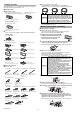
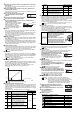
φ10
+0.005
+0.1
Nut
mounting
side
*1 For head mounting bracket C *2 Processing accuracy : ±0.05
φ10 G8
( )
*1
+0.005
+0.027
0.5 to 1.0
*2
5.5 to 11.3
*2
A
45°
±1°
φ0.025
A
(Unit: mm)
Tightening
sleeve
insertion
side
φ10
+0.005
+0.1
0.5 × 45°
recession
5.5 ∼ 11
Nut
mounting
side
Sensor head
insertion side
(Unit: mm)
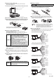
●
GT2-P12K(L)/P12(L)/PA12K/PA12/
H12K(L)/H12(L)/A1K2(L)/A12(L)
A
φ14
+0.1
+0.006
0.5 to 1.0
*2
5.5 to 11.3
*2
45°
±1°
φ0.025
A
(Unit: mm)
Nut
mounting
side
Tightening
sleeve
insertion
side
●
GT2-H32(L)/H50/A32/A50
●
GT2-P12KF/P12F/H12K(L)F/H12(L)F
Tightening sleeve
Nut
Chamfered side
Sensor head
Chamfered side
Nut
Key wrench
Dust boot
Wrench
8.5
8
+
0
.
2
0
0
+
0
.
0
0
5
M
4
x
0
.
7
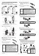
Make sure that the metal plating
mounting bracket F attaches to is made
of SUS (SUS303 recommended) and is
at least 5 mm thick.
•
GT2-P12K(L)/P12(L)/PA12K/PA12
NOTICE
• Make sure that the dust boot does not become
damaged during the procedure.
• When loosening the screw with the hexagonal wrench,
insert the long end of the hexagonal wrench into the
hex screw and rotate the small end with your hand.
• Do not forcibly tighten the hex screw.
• Cannot be used with GT2-P12KF/P12F/H***/A***.
NOTICE
• If the sleeve is inserted from the wrong side, the
sensor head cannot be secured.
• Strongly tightening the nut without the sensor head
inserted may deform the tightening nut.
• Head mounting bracket B cannot be used in
combination with head mounting bracket C (OP-
84396) or head mounting bracket D (OP-84327).
NOTICE
Tightening the nut while fixing the sensor head may
lead to damage.
• Apply a tightening torque of 5 to 7 N•m (the
recommended tightening torque is 5 N•m).
Use the wrench that fits the width of the nut.
• Care must be taken not to damage the dust boot when tightening.
NOTICE
• Never apply tightening torque over 1.4 N•m.
• Care must be taken not to damage the dust boot when tightening.
NOTICE
If the dust boot is not straight, it becomes easier to
damage when the spindle is moved.
Mounting illustration
Tightening sleeve Nut Mounting bracket
Optional head mounting bracket B
(OP-76875)
Tightening sleeve
Mounting bracket
Nut
Notice the correct angle of the tightening sleeve.
Nut
Wrench
Dust boot
M4 screws