
User Manual

4
GT2-70-M-E
Connecting and Mounting the Sensor Head
■
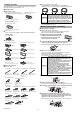
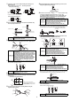
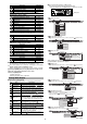
Names of parts of the sensor head
* Not included in the GT2-P12KL/P12L.
●
GT2-H12K(L)(F)(LF)/H12(L)(F)(LF)/H32(L)/H50
●
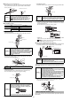
GT2-A12K(L)/A12(L)/A32/A50
■
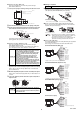
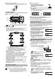
Connecting the sensor head connection cable
●
For GT2-P***/PA***
1
Insert the sensor head connection cable
into the cable connector on the relay
connector cable.
2
Secure the connector with the sensor
head connection cable screw.
●
For units other than GT2-P***/PA***
1
Insert the sensor head connection
cable into the cable connector of the
sensor head.
2
Secure the connector by rotating the
grooved portion.
To disconnect the sensor head connection cable, reverse the steps above.
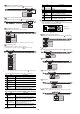
■
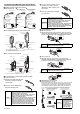
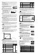
Connecting the amplifier
●
DIN rail mount type
1
Remove the lock cover of the connector of the sensor head
connection cable, and insert the sensor head connection cable
into the connector on the side of the amplifier until it clicks.
2
Put the lock cover on the connector, and lock the lock cover.
●
Panel mount type
1
Remove the lock cover of the connector of the sensor head
connection cable, and insert the sensor head connection cable into
the connector on the back of the amplifier until it clicks.
2
Put the lock cover on the connector, and lock the lock cover.
■
Mounting the sensor head
●
Mounting directly to the jig
Before mounting the sensor head directory to the jig, create a hole in the
jig. Attach the sensor head using the optional head mounting bracket
sold separately. A mounting bracket is provided with the GT2-P12KF/
P12F/H12K(L)F/H12(L)F as standard. Attach it with the supplied nut.
NOTICE
•W
hen connecting the connector, be sure to insert it
straight, and tighten it securely. (Recommended
tightening torque: 0.4 to 0.5 N•m*)
If the connection is not tight enough, the connector
may be loosened by vibration or other causes,
leading to a connection failure.
(* After tightening it firmly by hand, use pliers or other
tools to rotate it about 30° for further tightening.)
• When the head is attached to a moving part, and the
cable will be repeatedly bent, ensure that the cable
between the sensor head and relay connector does
not bend. Instead, bend the sensor head cable
connecting the relay connector and the amplifier.
Operation indicator
Relay connector
Cable
connector
Dust boot
Mounting fixture
Dust boot
※
Spindle
Contact
Dust boot
●
GT2-P12K(L)/P12(L)
●
GT2-P12KF/P12F
Cable between
the sensor
head and relay
connector
●
GT2-P
A
12K/P
A
12
Relay connector
Cable
connector
Cable
connector
Cable
between the
sensor head
and relay
connector
Operation indicator
Cable between
the sensor
head and relay
connector
Mounting fixture
Operation indicator
Contact
Spindle
Air supply hole
Dust seal
*1 A mounting bracket is attached to
GT2-H12KF/H12F/H12KLF/H12LF.
*2 Not included in the GT2-H12KL/H12L/H12KLF/H12LF.
Contact
Head indicator
Cable connector
mounting fastener*
1
Dust boot*
2
*3 Not included in the GT2-H32L.
Contact
Head indicator
Cable connector
mounting fastener
Dust boot*
3
Contact
Dust boot
Spindle
Dust boot
Dust boot*
Dust boot
Coupling socket
Coupling socket
Air cylinder
Air cylinder
Head indicator
Head indicator
Cable connector
Cable connector
Exhaust valve
Exhaust valve
Spindle
Contact
Mounting fixture
Mounting fixture
Contact
Contact
* Not included in the GT2-A12KL/A12L.
NOTICE
• When connecting the connector, be sure to insert it
straight, and tighten it securely. (Recommended
tightening torque: 0.4 to 0.5 N·m*)
If the connection is not tight enough, the connector
may be loosened by vibration or other causes,
leading to a connection failure.
(* After tightening it firmly by hand, use pliers or other
tools to rotate it about 30
o
for further tightening.)
• The M8 L-shaped connector (GT2-CHL*M) cannot be
used with the GT2-H32(L)/H50/A32/A50.
NOTICE
To disconnect the sensor head connection cable,
press and hold the lock lever on the side of the
connecter and disconnect the cable.
NOTICE
To disconnect the sensor head connection cable,
press and hold the lock lever on the side of the
connecter and disconnect the cable.
Arrow
Unlocked
Click
Lock cover
Locked
Lock cover
Orient the connector so that the lock lever is at the left side.
Unlocked
Lock cover
Click
Locked
Lock cover
Tightening sleeve
Key wrench
Nut
Optional head mounting
bracket A (OP-76874)
Tightening sleeve
Key wrench
Nut
Optional head mounting
bracket D (OP-84327)
Tightening sleeve
Key wrench
Nut
Optional head mounting
bracket C (OP-84396)
●
GT2-P12K(L)/P12(L)/PA12K/PA12/
H12K(L)/H12(L)/A12K(L)/A12(L)
●
GT2-H32(L)/H50/A32/A50
NOTICE
When mounting the GT2-
H32L facing upward, be
sure to use the mounting
holes on the side of the
sensor head. If the
sensor head is mounted
using head mounting
bracket D, the spindle
may not fully extend.
Mounting
illustration