
User Manual

16
GT2-70-M-E
■
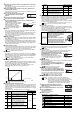
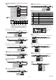
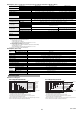
Analog output circuit diagram
GT2-71MCN/71MCP
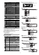
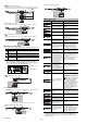
■
External input circuit diagram
GT2-71(M)(C)N/72(C)N/75N/76N
GT2-71(M)(C)P/72(C)P/75P/76P
Pulse Output Type Circuit Diagram
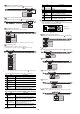
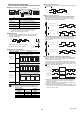
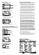
■
I/O circuit diagram
GT2-71D
■
External input circuit diagram
GT2-71D
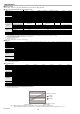
■
Recommended input device
Line receiver AM26LS32 or equivalent
WARRANTIES AND DISCLAIMERS
(1) KEYENCE warrants the Products to be free of defects in materials and
workmanship for a period of one (1) year from the date of shipment. If any
models or samples were shown to Buyer, such models or samples were
used merely to illustrate the general type and quality of the Products and
not to represent that the Products would necessarily conform to said
models or samples. Any Products found to be defective must be shipped to
KEYENCE with all shipping costs paid by Buyer or offered to KEYENCE
for inspection and examination. Upon examination by KEYENCE,
KEYENCE, at its sole option, will refund the purchase price of, or repair or
replace at no charge any Products found to be defective. This warranty
does not apply to any defects resulting from any action of Buyer, including
but not limited to improper installation, improper interfacing, improper
repair, unauthorized modification, misapplication and mishandling, such as
exposure to excessive current, heat, coldness, moisture, vibration or
outdoors air. Components which wear are not warranted.
(2) KEYENCE is pleased to offer suggestions on the use of its various
Products. They are only suggestions, and it is Buyer's responsibility to
ascertain the fitness of the Products for Buyer’s intended use. KEYENCE
will not be responsible for any damages that may result from the use of the
Products.
(3) The Products and any samples ("Products/Samples") supplied to Buyer are
not to be used internally in humans, for human transportation, as safety
devices or fail-safe systems, unless their written specifications state
otherwise. Should any Products/Samples be used in such a manner or
misused in any way, KEYENCE assumes no responsibility, and additionally
Buyer will indemnify KEYENCE and hold KEYENCE harmless from any
liability or damage whatsoever arising out of any misuse of the Products/
Samples.
(4) OTHER THAN AS STATED HEREIN, THE PRODUCTS/SAMPLES ARE
PROVIDED WITH NO OTHER WARRANTIES WHATSOEVER. ALL
EXPRESS, IMPLIED, AND STATUTORY WARRANTIES, INCLUDING,
WITHOUT LIMITATION, THE WARRANTIES OF MERCHANTABILITY,
FITNESS FOR A PARTICULAR PURPOSE, AND NON-INFRINGEMENT
OF PROPRIETARY RIGHTS, ARE EXPRESSLY DISCLAIMED.
IN NO EVENT SHALL KEYENCE AND ITS AFFILIATED ENTITIES BE
LIABLE TO ANY PERSON OR ENTITY FOR ANY DIRECT, INDIRECT,
INCIDENTAL, PUNITIVE, SPECIAL OR CONSEQUENTIAL DAMAGES
(INCLUDING, WITHOUT LIMITATION, ANY DAMAGES RESULTING
FROM LOSS OF USE, BUSINESS INTERRUPTION, LOSS OF
INFORMATION, LOSS OR INACCURACY OF DATA, LOSS OF
PROFITS, LOSS OF SAVINGS, THE COST OF PROCUREMENT OF
SUBSTITUTED GOODS, SERVICES OR TECHNOLOGIES, OR FOR
ANY MATTER ARISING OUT OF OR IN CONNECTION WITH THE USE
OR INABILITY TO USE THE PRODUCTS, EVEN IF KEYENCE OR ONE
OF ITS AFFILIATED ENTITIES WAS ADVISED OF A POSSIBLE THIRD
PARTY’S CLAIM FOR DAMAGES OR ANY OTHER CLAIM AGAINST
BUYER. In some jurisdictions, some of the foregoing warranty disclaimers
or damage limitations may not apply.
BUYER'S TRANSFER OBLIGATIONS:
If the Products/Samples purchased by Buyer are to be resold or delivered
to a third party, Buyer must provide such third party with a copy of this
document, all specifications, manuals, catalogs, leaflets and written
information provided to Buyer pertaining to the Products/Samples.
E 1101-3
Main circuit
Green*
Orange
Analog output (4 to 20 mA)
0V
* The green line is internally common with the blue line.
Blue*
1
Pink: Preset input
Violet: Bank A input
Pink/Violet: Timing input
Yellow: Bank B input
Red: Reset input
(Short circuit current: 1 mA max.)
*1 Blue is available for main units (GT2-71(M)(C)N/75N) only.
Not available for expansion units (GT2-72(C)N/76N).
Main
circuit
DC5V
*1 Brown is available for main units (GT2-71(M)(C)P/75P) only.
Not available for expansion units (GT2-72(C)P/76P).
Brown*
1
Pink: Preset input
Violet: Bank A input
Pink/Violet: Timing input
Yellow: Bank B input
Red: Reset input
(Short circuit current: 2 mA max.)
DC10-30V
Main circuit
* Refer to external input circuit diagram for details about external input.
Input circuit
Pink*
Blue
Brown
DC5V
33Ω
33Ω
Black, White, Orange
Violet, Gray, Green
Black: A phase
White: B phase
Orange: Z phase
Violet: A
_
phase
Gray: B
_
phase
Green: Z
_
phase
Pink: Input
Main circuit
Blue
Pink
Main
circuit
(Short circuit current: 1 mA max.)
DC5V
390Ω
Copyright (c) 2014 KEYENCE CORPORATION. All rights reserved.
96M12751E 1124-1 96M12752 Printed in Japan