
User Manual

13
GT2-70-M-E
GT2-71D (pulse output type)
■
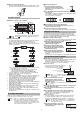
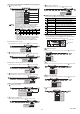
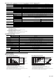
Names of parts of the amplifier
* An error occurs in the following situations.
• For 700 ms after power turns on (power on reset time)
• Head is not connected or becomes disconnected
• Overcurrent flows through the output
■
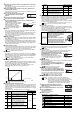
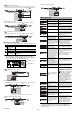
Output signal
The signals output by GT2-71D are A, B, and Z phase signals,
which are voltage differential format line driver output that is
compliant with EIA-422.
Z phase turns on when the sensor head
spindle is detected at home position.
■
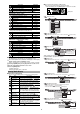
Advanced setting switch
Perform pulse output settings with the advanced setting switch.
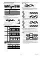
●
Minimum phase difference
Set the minimum phase difference of phase A and phase B (phase
A
and phase B ).
●
Pulse fluctuation Direction
Direction where pulse increases when the spindle contracts
When advanced setting switch 5 is turned off (factory default
setting), the pulse increases when the spindle contracts, and the
pulse decreases when the spindle extends.
Direction where pulse increases when the spindle extends
When advanced setting switch 5 is turned on, the pulse increases
when the spindle extends, and the pulse decreases when the
spindle contracts.
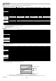
■
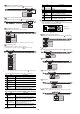
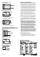
Current position notification output function
When the automatic current position request input line (pink wire) is
turned off from on, a pulse is output from the home to the current
mechanical position of the spindle.
This function can be used when there is a difference between the
counter value and the measurement position, such as cases where
the power is turned off during measurement or other troubles occur.
"Power cable (I/O cable)" (page 3)
(1) When the automatic current position request input (pink wire) is
turned off, the pulse of the spindle is output according to the
amount of movement.
(2) When the automatic current position request input (pink wire) is
turned on, all pulse outputs are turned off.
(3) When the automatic current position request input (pink wire) is
turned from on to off, the number of pulses from the home to the
current position is output.
Item Description
Power/alarm
indicator
Lights up green when the power is turned on.
Flashes red when there is an error*.
Pulse delivery
indicator
Flashes green when delivering a pulse.
Input indicator
Lights green when there is current position
request input.
Advanced setting
switches
Sets the advanced information for pulse output.
Setting item
Switch No.
Description
Minimum
phase
difference
1
Set A phase or B phase (A
phase or B phase)
as the minimum phase difference.
* This is the factory default setting.
2
Pulse
resolution
3
Set the pulse resolution.
* This is the factory default setting.
4
Pulse
fluctuation
direction
5
Sets the pulse fluctuation direction over the
operation direction for the sensor head spindle.
* This is the factory default setting.
(Not used) 6 ------------------------
Reference
When using a sensor head other than GT2-
P12K(L)(F)/PA12K/H12K(L)(F)(LF)/A12K(L), even if
the pulse resolution is set to 0.1
µ
m, a resolution of
0.5
µ
m is used.
Input indicator
Pulse delivery indicator
Power/alarm indicator
Advanced setting switches
Phase A
Phase B
Phase Z
Home position
(Set as a factory default;
it cannot be changed.)
ON
12
ON
12
ON
12
ON
12
0.5µs 2.5µs* 5µs 25µs
ON
34
ON
34
ON
34
ON
34
0.1µm 0.5µm* 1µm 10µm
ON
5
ON
5
Pulse expands when the
spindle is pushed in*
Pulse shrinks when the
spindle is pushed in
Phase A /phase B
minimum phase
difference
Phase A cycle
Allowable
frequency of the
counter
0.5µs 2µs 500kHz
2.5µs 10µs 100kHz
5µs 20µs 50kHz
25µs 100µs 10kHz
Phase A
Phase B
Minimum phase difference: 2.5 μs
ON
OFF
ON
OFF
Phase A (Black wire)
Phase B (White wire)
ON
OFF
ON
OFF
Phase A (Black wire)
Phase B (White wire)
ON
OFF
ON
OFF
Phase A (Black wire)
Phase B (White wire)
ON
OFF
ON
OFF
Phase A (Black wire)
Phase B (White wire)
ON
OFF
(1) (2) (3)
ON
OFF
ON
OFF
ON
OFF
Phase A
(Black line)
Current position
request input
Phase B
(White line)
Phase Z
(Orange line)