
User Manual

12
GT2-70-M-E
■
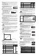
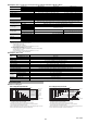
Calibration setting mode
You can set the following functions in the calibration setting mode.
●
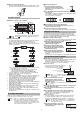
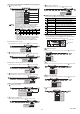
How to enter the calibration setting mode
Enter the calibration setting mode by the following procedure.
•
In the main display, press the [MODE] button and the right Arrow
button at the same time for at least two seconds.
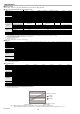
Error message
*1 If not recovered by this action, there may be a possibility of a failure
or permanent damage. In this case, change the amplifier unit.
*2 Bank switching, reset input, and preset input are available even
during "com.Loc".
No.
Item Description
Calibration
function setting
Set the calibration function.
-
1st point
detection/capture
Set the zero point (1st point).
2nd point target value
Set the target value of the span adjustment (2nd point).
-
2nd point
detection/capture
Set the detection position for the span
adjustment.
OFF
Jam detection function
ON
User
MODE
Not available to set on the main unit that selects "CAL.noH" in [ Calculation mode], and
the main unit and expansion unit that selects values other than "t-in" in [ Timing type].
Reference
position fixed
Jam detection teaching
Only available when "USEr" is selected in [ Jam detection function].
MODE
Setting value
input screen
Only available when "USEr" is selected in [ Jam detection function].
Jam detection check point setting
GT2-71
Right Arrow button
[MODE] button
Main screen
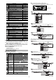
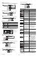
Default
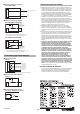
Adjustment
Calibration function setting
MODE
Detect 1st point
Blink alternately
Capture the
detection value
1st point detection/capture
Only available when "AdJ" is selected in [ Calibration function setting].
*Target value for the first point is the preset value.
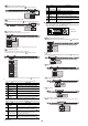
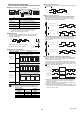
Setting value
input screen
2nd point target value setting
MODE
Error display Cause Corrective action
The sensor head cable is
disconnected.
Connect the sensor head to the
amplifier.
• The sensor head cable is broken.
• The sensor head is damaged.
Change the cable or sensor
head.
An overcurrent is present
in the output line.
• Check that the load is within the rating.
• Check that the output line is not
contacting other lines and frames.
Failed to write/read data.
Recycle power to the equipment
and perform initialization.
*
1
Spindle movement is not detected
• If something is caught in the spindle, causing the
spindle not to move, change the sensor head.
• Check the external timing input. (Press the
SET button to reset.)
The value fell below (rose
above) the timing level
during the delay time.
Change the delay timer time
setting. (Press the SET button
to reset.)
When setting the internal
timing, detection was
completed when the value fell
below (rose above) the timing
level before the criterion value
(P.V. value) is fixed.
The value should not fall below (rise
above) the timing level before the
criterion value is fixed. Alternatively,
lengthen the static hold delay
stabilizing amplitude so that the
criterion value can be easily fixed.
Contact between the
amplifiers is lost.
After turning OFF the power, check the
connection between the amplifiers.
• In the case of using the
calculation function, the number
of the expansion unit when the
power is turned ON differs from
the number of the expansion
unit in the memory of the main
unit when the calculation is set.
• When using the calculation
function, a model other than the
GT2 Series is added.
• Reset the calculation mode or
perform the initial reset of the
main unit.
• After turning OFF the power,
check the connections
between the amplifiers.
• When using the reference difference
(rEF) calculation function, an error
occurred in the main unit.
• When using other than the reference
difference (rEF) calculation function, an
error occurred in an expansion unit.
Check each main/expansion
unit for the cause of the error.
The sensor head is connected
to the main unit in which the
calculation only mode is set.
Remove the sensor head from the
main unit or set the mode other
than the calculation only mode.
"com.Loc" is displayed
and cannot change the
setting.
The read/write setting switch of
the connected communication
unit DL-RS1A is set to RW.
*2
Set
the read/write setting switch to R.
Refer to "RS-232 Communication
Unit DL-RS1A User's Manual"
Displayed when this equipment is
accessed (operation command/
settings and status writing/keylock) via
<DL-CL1>, <DL-DN1> or <DL-EP1>.
The buttons are locked, but after
approximately 10 seconds, "com.unLoc"
is displayed on the amplifier and the
buttons are unlocked.
*2
The calculation mode is
used, so the function
setting mode cannot be
changed
Check the calculation mode settings
again.The function setting mode can be
changed only when the calculation mode of
the main unit is set to C0. oFF or C5. rEF.
The criterion value (P.V.
value) becomes "------"
during the tolerance tuning.
Perform the timing input and fix
the criterion value, and then
perform the tolerance tuning.
The hold detection is selected or the
timing input is not performed, so the
criterion value (P.V. value) is not fixed.
Perform the timing input.
The operations of the expansion unit
are locked while the simultaneous
input is selected and the keylock is
activated on the main unit.
Deactivate the keylock on the
main unit.
After ALL GO is selected in
the special output setting,
the number of expansion
units changed.
• If the number of expansion units
has been changed, set the special
output setting again.
• If the number of expansion units has
not been changed, check if each
expansion unit operates correctly,
then turn on the power again.
Detect 2nd point
Blink alternately
Capture the
detection value
2nd point detection/capture