
User Manual

1
GT2-70-M-E
High-accuracy Digital Contact Sensor
GT2-70
Series Instruction Manual
■
Symbols
The following symbols alert you to matters concerning the prevention of
human injury and product damage. Be sure to read these messages carefully.
Safety Information for GT2-70 Series
■
Other precautions
●
Effects of surrounding air temperature
To use the GT2-70 Series with high accuracy, do not use the GT2-70 Series in
an environment in which the surrounding air temperature changes sharply.
It will take about 40 minutes for the 12 mm type, and 60 minutes for the 32 mm/50 mm type for
the internal temperature to stabilize when the surrounding air temperature has changed by 10°C.
●
Warming up
The circuit is not stable immediately after the power turns ON, which
sometimes causes the indicated value to gradually fluctuate. Wait for about
5 minutes when using the 12 mm type and about 10 minutes when using
the 32/50 mm type after the power turns on before starting operation.
●
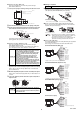
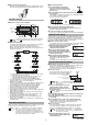
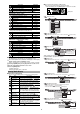
GT2-PA12K/PA12 (See illustration 1 for the pneumatic circuit)
•
This model uses a single-acting cylinder. The internal spring will
return the sensor head to its home position.
•
The air supply hole cannot be removed.
•
Use an air filter, mist separator, etc. to provide clean dry air. Empty the
drainage from the filter regularly, before it exceeds the specified line.
•
Before connecting the air tube to the air supply hole, be sure to blow
plenty of air through the pipes (flushing) to remove any foreign matter.
•
Make sure that the air pressure of the supplied air is constant and in the range
of 0.24 to 0.26 MPa. Use a precision regulator to control the air pressure. If
the air pressure is below 0.24 MPa, the spindle may not extend fully.
•
When supplying air (with the spindle extended), up to 3L/min of air
will be emitted from the tip of the dust seal.
•
The measuring ability of the device changes according to the air pressure
of the air supply. Refer to "Specifications" (page 14) for details.
●
GT2-A12K(L)/A12(L)/A32/A50 (See illustration 1 for the pneumatic circuit)
•
This model uses a single-acting cylinder. The internal spring will return the sensor head to
its home position when air pressure is removed. DO NOT supply air to the exhaust valve.
•
The air cylinder cannot be removed.
•
Use the regulator to supply the stable air pressure to the sensor head.
•
Use the air filter and mist separators to supply dry air. Empty the
drainage from the filter regularly, before it exceeds the specified line.
•
Make sure that the air pressure of the supplied air is constant and
in the range of 0.25 MPa to 0.5 MPa.
•
The coupling socket and the exhaust valve that are supplied with the
air cylinder are dedicated for this product. They cannot be removed.
●
Power supply
•
Noise superimposed on the power supply may cause malfunction. Be sure to
use the DC stabilized power supply provided with an insulation transformer.
•
In the case of a commercially available switching regulator, be sure to
ground the frame ground terminal or the ground terminal.
●
About dust boot
When the dust boot of the sensor head is damaged, use an optional dust boot sold
separately (For GT2-P12K(F)/P12(F)/H12K(F)/H12(F)/A12K/A12: OP-84332 (Material: NBR
(attached when shipped)). For GT2-P12K(F)/P12(F): OP-87859 (Material: Fluororubber).
For GT2-H32/A32: OP-84459 (Material: NBR (attached when shipped)). For GT2-
H50/A50 (Material: NBR (attached when shipped)).) Attach the dust boot correctly.
The dust boot may deteriorate, depending on the environment it is
used in. In this case, replace the dust boot regularly.
* Do not use the dust boot on the GT2-P12KL/P12L/PA12K/PA12/H12KL(F)/H12L(F)/H32L.
Precautions on Regulations and Standards
■
CE Marking
●
EMC Directive (2004/108/EC)
•
Applicable standard EMI: EN61326-1, Class A
EMS: EN61326-1
•
This product is designed for use in industrial environments.
Remarks
:
This specification does not give any guarantee that the end-product
with this product incorporated complies with the essential requirements of
EMC Directive. The manufacturer of the end-product is solely responsible for
the compliance on the end-product itself according to EMC Directive.
■
UL Certificate
UL File No. E120439 (Category: NRNT2/NRNT8)
•
Use the power supply with Class 2 output defined in NFPA70
(NEC: National Electrical Code).
•
GT2 series are evaluated as open type devices. These products
can not be a part of an enclosure.
WARNING
It indicates a hazardous situation which, if not avoided,
could result in death or serious injury.
NOTICE
It indicates a situation which, if not avoided, could result in
product damage as well as property damage.
WARNING
If the following conditions are encountered, immediately turn
OFF the power. Continuing to use the GT2-70 Series under
these abnormal conditions may cause equipment failure.
• When water or foreign matter enters the controller
• When the GT2-70 Series is dropped or the housing is damaged
• When the GT2-70 Series produces smoke or an abnormal smell
WARNING
• Do not use the GT2-70 Series with a voltage other than
specified voltage, as this may cause fire, electric shock
or equipment failure.
• Do not disassemble or modify the GT2-70 Series. This
may cause fire or electric shock.
• Do not use this product for the purpose to protect a
human body or a part of human body.
• This product is not intended for use as explosion-proof
product. Do not use this product in a hazardous location
and/or potentially explosive atmosphere.
NOTICE
• Be sure to turn OFF the power of the GT2-70 Series and any
connected devices before connecting or disconnecting the
cables. Otherwise, there may be a risk of damage.
• Do not turn OFF the power while setting parameters.
Otherwise, the settings may be partially or completely lost.
• At startup and during operation, be sure to monitor the
function performance of the GT2-70 Series.
• Do not modify the GT2-70 Series or use it in any way
other than described in the specifications.
• The function performance of products used or modified
in this way cannot be guaranteed.
• When the GT2-70 Series is used in combination with other
instruments, function performance may be degraded,
depending on operating conditions and the surrounding
environment. Use the GT2-70 Series after fully studying
the effect of combined use with other instruments.
• Do not expose the GT2-70 Series and peripheral devices
to sudden temperature change. This may cause
condensation, damaging the equipment.
●
Environmental conditions
To use the GT2-70 Series properly and safely, do not
install the GT2-70 Series in the following locations. Use
of this equipment in an improper environment may
cause equipment failure.
•
Locations outside
•
Locations with high humidity, a large amount of dust,
or poor ventilation
•
Locations where the temperature rises excessively
due to direct sunlight, etc.
•
Locations near corrosive or flammable gas
•
Locations where the GT2-70 Series is directly
subjected to vibration or impact
•
Locations where water, oil or chemicals may come
into contact with the GT2-70 Series
•
Locations where static electricity may easily occur
●
Noise countermeasures
Installation near a source of electrical noise such as a
power source or a power cable may cause malfunction
or failure of the equipment. Adopt appropriate
countermeasures against noise by using a noise filter
or wiring cables in separate ducts, attaching insulation
to the amplifier or the sensor head, etc.
NOTICE
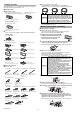
●
Handling of the sensor head
•
The GT2-70 Series and peripheral devices are precision
machines. Do not drop, or cause any other impact to these
devices. Doing so may cause damage or malfunction.
•
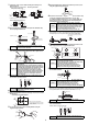
Do not apply weight greater than what is listed below to the spindle.
Do not apply rotational torque. Otherwise the spindle may break.
•
The GT2-P12KL(F)/P12L(F)/PA12K/PA12 spindle can rotate a
maximum of about 4.5°. When using an offset contact (OP-
77683) or similar, if pressure in the rotational direction is
applied to the contact, the measurement position may change.
•
Although the GT2-PA12K/PA12/H12K/H12KF/H12/H12F/
H32/H50/A12K/A12/A32/A50 has a protection rating of
IP67, avoid using it immersed in water or in places where
liquid such as oil may come into contact with it.
•
Although the GT2-P12K(F)/P12(F) has a protection rating of
IP67G/NEMA Type 13, some types of oil may damage the device.
•
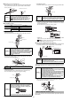
If dust, metal powder, or similar becomes attached to the sliding part
of the sensor head, mechanical responses may become slow. If this
happens, replace the dust seal with a replacement dust seal (OP-
87932). Refer to the instruction manual included with the replacement
dust seal (OP-87932) for instructions on how to replace the dust seal.
30 N 100 N
1 N
Mist separator
Air filter
Pressure
source
AIR
Solenoid
valve
Precision regulator
Air supply part
Speed
controllerIllustration 1 - Pneumatic circuit
96M12752