
Owner manual

4
GT2-100-M-E
3
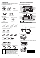
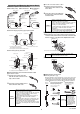
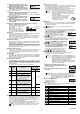
Attach the head expansion board with the screws.
Attach the head expansion board with the two M3 screws used to
mount the cover.
To remove the head expansion board, reverse the steps above.
■
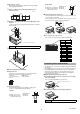
Assigning the head ID No.
The head ID No. is assigned according to the position of the
connector to which the head is connected.
■
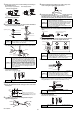
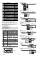
Mounting the I/O connector for expansion units
For the input and output of the GT2-E3N/E3P, use OP-84456 (MIL
socket connector 30-pin) sold separately.
For the information on how to assemble the connector and how to
connect the power cable, refer to "GT2-100 Series User's Manual".
●
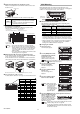
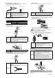
Pin arrangement of I/O connector
For details about the I/O circuit, refer to page 15 of this instruction manual.
Valid ID Setting
On the GT2-100 Series, the expansion unit head ID No. is pre-
assigned. When turning on the power for the first time or changing the
number of connected sensor heads, set the valid ID.
■
Default values of the valid ID
The initial value of the valid ID setting varies depending on the
number of head expansion boards.
•
When using the unit with the initial values, connect the maximum number
of sensor heads. When the number of the connected sensor heads is
less than the valid number of connected units, "ErH (head connection
error)" appears along with the ID to which no sensor head is connected.
•
When the number of the connected sensor heads is less than the
maximum number of connected units, change "27. id (Valid ID
Setting)" in the additional function setting mode.
■
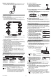
Changing the valid ID
1
Turn on the power.
The main display appears.
2
Press the [MODE] button and the
left Arrow button at the same time
for at least two seconds.
The GT2-100 Series enters the
additional function setting mode.
3
Press the right Arrow button
until “27. id” appears.
The valid ID setting mode is
displayed.
4
Press the top/bottom Arrow
buttons once.
The current setting value is
displayed.
5
Press the top/bottom Arrow
button to select valid IDs.
.
6
Press the [MODE] button (or click the right Arrow button) to
exit the valid ID setting mode.
When the setting is completed,
press the [MODE] button again
to exit the additional function
setting mode. The usable head
ID indicator and its head OK/
NG indicator turn on.
NOTICE
• Apply tightening torque of 0.5 to 0.7 N•m
• Be sure to attach the head expansion board with
screws.
• Be sure to connect the head expansion boards
sequentially from the upper slot.
Reference
• The assigned head ID No. cannot be changed.
• Be sure to connect the sensor heads sequentially
without skipping a connector. If the head expansion
board has a connector to which no sensor head is
connected, disable the unused connector in the
valid ID setting.
• The sensor heads exceeding the IDs set in the valid
ID setting cannot be recognized.
Fix with screws
ID 00 ID 01
ID 02 ID 03 ID 04
ID 05 ID 06 ID 07
ID 08 ID 09 ID 10
I/O connector for
expansion unit: ID 02 to 04
I/O connector for
expansion unit: ID 05 to 07
I/O connector for
expansion unit: ID 08 to 10
I/O connector for
main unit: ID 00 / expansion unit: ID 01
Sensor head connectors
(When connecting the I/O connector)
(When disconnecting the I/O connector)
2927252321191715131197531
30282624222018161412108642
ID:4 ID:3 ID:2
Pin
No.
Signal name
Pin
No.
Signal name
Pin
No.
Signal name
1 HIGH output 11 HIGH output 21 HIGH output
2 LOW output 12 LOW output 22 LOW output
3 GO output 13 GO output 23 GO output
4 HH output 14 HH output 24 HH output
5 LL output 15 LL output 25 LL output
6 PRESET input 16 PRESET input 26 PRESET input
7 BANK A input 17 BANK A input 27 BANK A input
8 BANK B input 18 BANK B input 28 BANK B input
9 RESET input 19 RESET input 29 RESET input
10 TIMING input 20 TIMING input 30 TIMING input
Number of head
expansion boards
Initial
value
Maximum number of connecting
sensor heads
0 boards id = 1
Main unit: 1 unit, Expansion unit: 1 unit
1 board id = 4
Main unit: 1 unit, Expansion unit: 4 units
2 boards id = 7
Main unit: 1 unit, Expansion unit: 7 units
3 boards id = 10
Main unit: 1 unit, Expansion unit: 10 units
Reference
Be sure to operate while [0] on the head ID indicator lights in red.
"Amplifier display" (Page 8)
Reference
While setting the valid
IDs, the head ID indicator
of the expansion unit
currently set as the
available range blinks in
green, and the display "id
= **" appears on the
digital LED display.
Reference
The ID of the sensor head exceeding the IDs set in the
valid ID setting cannot be recognized.
For the unrecognized ID, its head ID indicator and its
head OK/NG indicator are turned off, and the unused
ID cannot be selected.
OK/NG indicator
for each Head No.
Head ID
indicator
[Head select]
button
The heads of ID 00 to ID 04 are available
When activating the heads of ID 00 to
03
When selecting the heads of ID 00 to
03
When valid ID = 3 is selected