
User guide

4
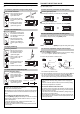
SETTING 2 INDEPENDENT OUTPUTS
The FS-V1(P) allows you to set two types of sensitivity (tolerance indi-
vidually.
To change the channel, press [UP] or [DOWN] while holding [MODE].
HINTS ON CORRECT USE
• To extend the cable length, use a cable with at least a 0.3 mm
2
cross-section area. Limit the length of cable extension to no more
than 100 m. (To connect several units, contact Keyence for further
information.)
• If the amplifier cable is placed together with power lines or high volt-
age lines in the same conduit, detection error may occur due to noise
interference, or the sensor may be damaged. Isolate the amplifier
cable from these lines.
• When using a commercially available switching regulator, ground the
frame ground terminal and ground terminal.
• Do not use the FS series outdoors, or in a place where extraneous
light can enter the light receiving surface directly.
• During maximum sensitivity setting, the detecting distance may vary
due to the difference in characteristics of each unit.
• When the stability output is not used, cut the orange cable at the root
or connect it to the 0 V (“+” for PNP output model) terminal of the
power supply, in order to avoid contact with other cables.
• When the external calibration is not used, cut the pink cable at the
root or connect it to the “+” (“0 V” for PNP output model) terminal of
the power supply, in order to avoid contact with other cables.
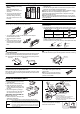
DIMENSIONS
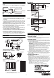
I/O CIRCUIT
FS-V1
(External calibration input circuit)
FS-V1P
(External calibration input circuit)
WARRANTY
KEYENCE products are strictly factory-inspected. However, in the event of a failure,
contact your nearest KEYENCE office with details of the failure.
1. WARRANTY PERIOD
The warranty period shall be for one year from the date that the product has been
delivered to the location specified by the purchaser.
2. WARRANTY SCOPE
(1) If a failure attributable to KEYENCE occurs within the above mentioned warranty
period, we will repair the product, free of charge. However, the following cases shall
be excluded from the warranty scope.
• Any failure resulting from improper conditions, improper environments, improper
handling, or improper usage other than described in the instruction manual, the
user’s manual, or the specifications specifically arranged between the purchaser
and KEYENCE.
• Any failure resulting from factors other than a defect of our product, such as the
purchaser’s equipment or the design of the purchaser’s software.
• Any failure resulting from modifications or repairs carried out by any person other
than KEYENCE staff.
• Any failure that can certainly be prevented when the expendable part(s) is
maintained or replaced correctly as described in the instruction manual, the
user’s manual, etc.
• Any failure caused by a factor that cannot be foreseen at a scientific/technical
level at the time when the product has been shipped from KEYENCE.
• Any disaster such as fire, earthquake, and flood, or any other external factor, such
as abnormal voltage, for which we are not liable.
(2) The warranty scope is limited to the extent set forth in item (1), and KEYENCE
assumes no liability for any purchaser’s secondary damage (damage of equipment,
loss of opportunities, loss of profits, etc.) or any other damage resulting from a
failure of our product.
3. PRODUCT APPLICABILITY
KEYENCE products are designed and manufactured as general-purpose products
for general industries.
Therefore, our products are not intended for the applications below and are not
applicable to them. If, however, the purchaser consults with us in advance regarding
the employment of our product, understands the specifications, ratings, and
performance of the product on their own responsibility, and takes necessary safety
measures, the product may be applied. In this case, the warranty scope shall be the
same as above.
• Facilities where the product may greatly affect human life or property, such as
nuclear power plants, aviation, railroads, ships, motor vehicles, or medical
equipment
• Public utilities such as electricity, gas, or water services
• Usage outdoors, under similar conditions or in similar environments
#
CH
D
CH
Channel A output
Channel B output
Black
White
Output lines for channels A and B
Unit: mm
18
4
6.7
2.1
(Maximum
when the
cover is
opened)
135
max.
(12.5)
(33)
1,1 6
28.5
35.48.4
53.5
DIN-rail mounting
12
min.
78
φ3.9 5-core x
Cable length: 2 m
Brown/Blue: 0.34 mm
2
Black/White/Pink: 0.18 mm
2
8
16
36.5
1.1
5
11.3
18.5
15
2 x φ3.4
12
min.
2 x (4.4 x 3.4)
15
18
15
29.4
618 6L
End unit
1.
End unit
2.
1
2
3
4
5
6
7
8
9
10
11
12
13
14
15
16
9
18
27
36
45
54
63
72
81
90
99
108
117
126
135
144
No. of units L
FS-V1(P)
When the mounting bracket
[included in FS-V1(P)] is attached:
Rear view of mounting
bracket
When several units are connected:
1. The FS-V1(P) is mounted in .
2. When using expansion units, be sure to use the end unit
(accessory to the expansions unit.)
12 to 24 VDC
Input circuit
Load
100mA max.
100mA max.
Load
Photoelectric sensor
main circuit
Overcurrent
protection circuit
Brown
Black
(Control output)
White
(Control output)
Blue
Pink (External calibration input)
12 to 24 VDC
3.3 kΩ
11 kΩ
Pink
0
V
Contact or solid
state input
12 to 24 VDC
Input circuit
Load
100mA max.
100mA max.
Load
Photoelectric sensor
main circuit
Brown
Black
White
Blue
Pink (External calibration input)
Overcurrent
protection circuit
3.3 kΩ
11 kΩ
0 V
Pink
12 to 24 VDC
Contact or solid
state input
2010
11226E 1080-1 96M11226