
User guide

3
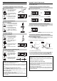
CONTROL AN EXPANSION UNIT [FS-T2(P)]
1. To change the channel, press
[UP] (or [DOWN]) while holding
[MODE].
Select the channel for the
expansion unit [FS-T2(P)] to be
controlled.
2. You can monitor the expansion
unit [FS-T2(P)] or change its
sensitivity setting value using
the same procedures as for the
FS-V1(P).
• You cannot use the FS-V1(P)’s SET button to set the sensitivity of the
expansion unit.
• The red LED and green LED turn ON and OFF in response to the
expansion unit [FS-T2(P)] turning ON and OFF.
Note 1: You cannot control the [FS-M2(P)] (Manual calibration model).
Note 2: The channel for the [FS-M2(P)] is displayed as “------”. The
red LED and green LED turn ON and OFF in response to the [FS-
M2(P)] turning ON and OFF.
Note 3: If you add an FS-V20 Series expansion unit, you may not be
able to control the FS-V20 Series and any expansion units added after
the FS-V20 Series .
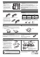
CONNECTING FIBER UNIT
Lower the quick-release lever, insert the fiber unit about 14 mm until it
reaches the end, and then lift the quick-release lever.
• To connect a fiber unit with a small diameter, use the adaptor
included with the FU series.
1. Attach the adaptor to the fiber
unit.
2. Fully insert the adaptor into the
mounting holes of the amplifier,
and then lift the quick-release
lever.
Note: If the fiber unit is improperly connected, the sensor cannot meet
the specifications.
• The required adaptor is included in each model of the FU series. If an
inadequate adaptor is used, the fiber unit cannot be properly installed.
• To connect the coaxial reflective type fiber unit to the amplifier, con-
nect the single-core fiber to the transmitter side, and connect the
multiple-core fiber to the receiver side.
(Connect the fibers according to the marking on the amplifier lateral side.)
MOUNTING MAIN UNIT
Mounting/Detaching the unit to/from a DIN rail or the
mounting bracket.
Hook the claw located at the unit cable side onto the DIN rail, and then hook the
front side claw to the rail while pressing the amplifier forward. To detach the
unit, unhook the front claw by lifting the unit front side while pressing it forward.
Mounting a unit laterally
Secure the screws through the mounting bracket’s side hole (accessory)
MUTUAL INTERFERENCE SUPPRESSION FUNCTION
When using several fiber units, each fiber unit is free from light
interference from up to 4 adjacent fiber units.
When the fiber units are mounted closely, each fiber unit and its 4 adja-
cent units are designed to receive light at different pulse frequencies to
avoid interference.
You can mount the FS-T(P) series and
the FS-M(P) series together within the
same system.
Note: If you do not use the expansion-
units, the mutual interference suppress
function is not available.
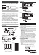
MOUNTING EXPANSION UNITS
Mounting EXPANSION units
1. Detach the protective cover from the
unit’s side panel.
2. Mount units to a DIN rail one by one.
3. Slide one expansion unit toward
another. Align the front claws of the
units and push the unit together until
they click.
4. Fix the units together by pushing an
end unit onto each end. (The end units
are included in the expansion unit)
Detaching units from DIN rail
1. Remove the end units.
2. Slide the expansion units apart, and
detach them individually.
(Do not detach multiple units connected together with end units.)
The sticker shown on the right is
included in the expansion unit. Apply
this sticker near the sensor.
AB
MODE
SET
# 2
CH
CH2 CH17CH4CH3
Expansion units
Channel
display
12
1
2
Cable outer dia. Type Shape
φ1.3
Adaptor A
(OP-26500)
φ1.0
Adaptor B
(OP-26501)
Multiple-core
Single-core
Transmitter
Receiver
Mounting Detaching
M3 screw
• When several units are connected, confirm the ambient temper-
ature. (See "Specifications" on P. 1.)
• To connect several units, be sure to use a DIN rail and end units.
• To mount or detach several units, be sure to turn the power off.
• Do not remove the protective cover of the expansion connector
on the outmost unit.
NOTICE
Main unit
Up to 16 expansion units
can be connected.
Remove the protective cover.
End unit
(Included
with FS-T2)
Expansion
unit
1. The FS-T1(P)/M1(P) can be used as the
same unit as well as the FS-V1(P).
2. FS-M2(P) can be used as the expansion unit
as well as the FS-T2(P).
1.
2.
Align the claw.
Slide the unit to the
right to remove it.