
Owner's manual
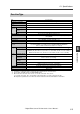

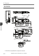


5-2 Input/Output Circuit Diagram
5
Specifications
5-7
- Digital Fiber Sensor FS-N10 Series User's Manual -
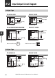
FS-N13CP/N14CP
0 V
12 to 24 VDC
* FS-N13CP only
Sensor main circuit
(Control output 2)
(Control output 1)
Overcurrent
protection circuit
Overcurrent
protection circuit
Load
Load
1
2
3
4
M8 connector Pin layout
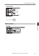
Monitor output type
FS-N11MN
0 V
12 to 24 VDC
Brown
Black
Monitor output
(1 to 5V)
*1
Orange
Blue
*1
Device with in
p
ut im
p
edance 10 kΩ or more
Sensor main circuit
Load
(Control output)
Overcurrent
protection circuit
Protection
circuit