
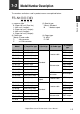
Owner's manual


2-1 Installing Sensor Amplifiers
2
Installation and Connection
2-4
- Digital Fiber Sensor FS-N10 Series User's Manual -
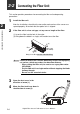
· Be sure to turn off the power before wiring.
· Insulate each input or output cable that will not be used.
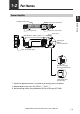
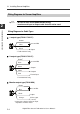
Wiring Diagrams for Cable Types
1-output type (FS-N11/N12)
2-output type (FS-N13/N14)
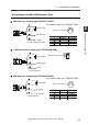
Monitor output type (FS-N11MN)
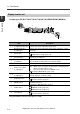
Wiring Diagrams for Sensor Amplifiers
Point
Brown
*
Output
Blue
*
Black
12 to 24 VDC
* FS-N11N/N11P only
Brown
*
Blue
*
Black
12 to 24 VDC
* FS-N13N/N13P only
Output1
External input
Output2
White
Pink
Brown
Blue
12 to 24 VDC
* Connect to a device having an input
impedance 10 kΩ or more.
Black
Output
Monitor output
(
1 to 5V
)
Orange
*