
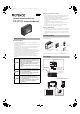
Manual

3
Connecting to an External Device
■ Connection
* Recommended communication cable:
KPEV-SP(1P) wire with balanced type twisted shield (strand wire)
Nominal cross-section area 0.16mm
2
(AWG25) min.
A terminal cover is attached to the terminal block. After
performing the wiring, be sure to reattach the terminal cover.
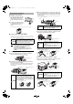
● Crimp-type terminal
Use Y or round terminals for wiring to the I/O terminal of the following sizes.
Y terminal
Round terminal
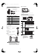
■ Wiring
To connect to an external device including a PC,
refer to the following wiring diagram for connection.
• The cable to be used for communication should be
15m or less.
• Be sure to connect the shield wire of the shield cable
to the SG terminal on the external device.
• The shield wire connected to SG terminal should not
contact with other signal cables or terminal blocks.
■ Input circuit diagram
* Pin No. 1, 4 and 5 (SG) are common to the 0V blue wire on the main
sensor amplifier.
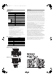
Communication Settings
Use the communication setting switch for communication settings.
• After changing the
communication settings, be
sure to cycle power.
• After setting, reattach the
included switch protection
sticker.
Terminal No. Terminal symbol Description
1SG
Connect the shield wire of the communication
cable. Terminals 1, 4 and 5 are internally
connected.
2 RD (input)
Connect to SD of an external device with the
communication cable.
3 SD (output)
Connect to RD of an external device with the
communication cable.
4 SG Terminals 1, 4 and 5 are internally connected.
5 SG Terminals 1, 4 and 5 are internally connected.
6 DRQ (input)
If terminals 6 (DRQ) and terminals 1, 4 or 5 (SG)
are short circuited, data is transmitted without a
command from an external device.
Excerpted from dimensions of the Y terminal areas
B: Outer size of Y area
d: Width of inner
Y area (joint area with screw)
Applicable dimension
B: 6mm max.
d: 3.2mm min.
Excerpted from dimensions of the round terminal areas
B: Outer size of round area
d: Diameter of inner round area
(joint area with screw)
Applicable dimension
B: 6mm max.
d: 3.2mm min.
KPEV-SP(1P) wire with balanced
type twisted shield (strand wire)
SG
RD
SD
SG
SG
DRQ
Communication cable
OP-81283
To an external device
Note
B
B
φd
d
SD
RD
DR
ER
RS
CS
SG
2
1
3
4
5
6
RD
SG
SD
SG
SG
DRQ
RS-232C Communication unit
DL-RS1A
External connecting
device (including a PC)
Shield
Note
Switch No.
Setting item Combination
1
Communication
speed
*Settings before shipment.
Do not use the switches No.1 to 3
in combinations other than those
shown above.
2
3
4 Data bit length
*Settings before shipment.
5
Parity check
*Settings before shipment.
6
(Short-circuit current 1mA max.)
6(DRQ)
+5V
1,4,5(SG)*
Main circuit
10
0
N
2
3
4
5
6
6
10
2
N
3
4
5
6
Communication setting switch
ON ON
ON
ON
ON
123 123 123 123 12 3
2400bit/s 4800bit/s 9600bit/s
*
19200bit/s 38400bit/s
Note
ON
4
ON
4
8bit * 7bit
ON
56
ON
56
ON
56
ON
56
None * Even Odd None
Note
Switch protection sticker
DL-RS1A_IM_E.fm 3 ページ 2008年12月10日 水曜日 午前11時45分