96081E RS-232C Communication Unit DL-RS1A User's Manual (IL Edition) Read this manual before using the system in order to achieve maximum performance. Keep this manual in a safe place for future reference.
Introduction This manual provides an overview of the RS-232C communication unit DL-RS1A and describes the functions and procedures of the unit. Be sure to read this manual carefully to ensure safe performance and function of the unit. Keep this manual in a safe place for future reference. Ensure that this manual is passed to the end user. Safety Precautions General Cautions • At startup and during operation, be sure to monitor the functions and performance of the DL-RS1A for proper operations.
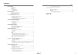
Contents Contents Safety Precautions T5 (Response send time from DL-RS1A) .................................................................................. 18 T6 (Sensor amplifier settings change time)............................................................................... 18 General Cautions Handling Errors Operating Precautions Specifications Performance Specifications ........................................................................................... 18 Communication Specifications..
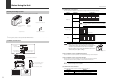
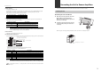
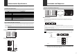
Before Using the Unit Before Using the Unit (1) Communication setup switches You can use different ON/OFF combinations to configure the communication settings. Checking the Package Contents Setting Switch No. Combination Before using the DL-RS1A, check that the following items are all included. 1 2400bit/s 4800bit/s ON 2 Baud rate ON 1 2 3 9600bit/s* ON 1 2 3 19200bit/s 38400bit/s ON ON 1 2 3 1 2 3 1 2 3 * Factory default positions are shown.
Connecting the Unit to Sensor Amplifiers Before Using the Unit This section describes how to mount a DL-RS1A and connect it to sensor amplifiers. (5) Alarm indicator This indicator lights up in red. For information on the actions you should take when an alarm occurs, refer to "Troubleshooting" (page 19). After turning on the power, the alarm indicator lights for the following amount of time, and communication cannot be performed during this time. No.
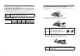
Connecting the Unit to Sensor Amplifiers Connecting the Unit to Sensor Amplifiers Connecting the DL-RS1A to DIN rail mount sensor amplifiers Connecting the Unit to Sensor Amplifiers 1 NOTICE Sensor amplifier Expansion protective cover Make sure that the sensor amplifiers are turned off before connecting the RS232C communication unit DL-RS1A to them. Connecting the unit while the sensor amplifiers are turned on may damage the unit.
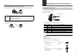
Connecting the Unit to External Devices Connecting the Unit to Sensor Amplifiers Connecting the unit to panel mount sensor amplifiers 1 Connect DL-RS1A to the sensor amplifiers using the optional expansion cable (OP-35361). Communication Terminal Block You can connect external devices such as a PC or PLC to the communication terminal block of DL-RS1A via the communication cables.
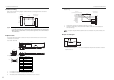
Connecting the Unit to External Devices Connecting the Unit to External Devices Connection wiring Sample wiring Refer to the connection wiring diagram shown below when connecting DL-RS1A to an external device such as a PC.
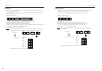
Communication Specifications Commands and Responses This section provides the communication specifications of DL-RS1A and describes how to configure the unit. Overview of Commands and Responses Communication Specifications ID No. 00 01 02 06 07 Main Exp. Exp. Exp. Exp. Command or DRQ input The following table lists the communication specifications for DL-RS1A.
Commands and Responses Commands and Responses Response Error response When DL-RS1A successfully receives a command from the external device, it automatically returns a response based on ASCII codes. For information on the parameters used in the response, refer to "Parameters of Commands and Responses" (page 10). If DL-RS1A could not receive a command from the external device or if the received command included an error, it automatically returns an "error response" based on ASCII codes.
Commands and Responses Commands and Responses Read with external input to the DRQ terminal (DRQ read) Reading You can send an input signal (by short-circuiting DRQ (terminal number 6) and SG (terminal number 1, 4, or 5)) from an external device such as a PLC instead of sending a command. External devices such as PLC's use the following communication commands to read data from DL-RS1A. Read from the specified sensor amplifier (SR command) Input signal SG Command RD ON SD S R ID No.
Parameters of Commands and Responses Commands and Responses This section describes the parameters used with various commands and responses. Writing Communication commands External devices such as PLC's use the following communication commands to write data to DL-RS1A. Point Attempting to write data with "read-only" attribute results in a communication error and an error response (error number: 22). There are two types of communication commands: read commands and write commands.
Parameters of Commands and Responses Parameters of Commands and Responses Data numbers *3 Specify the data number using three digits (ASCII characters). z Read-only data Bit The following table lists the types of data that can only be read from the IL Series sensor amplifiers. 0 1 2 3 4 5 6 7 8 9 10 11 12 13 Point Writing read-only data results in a communication error (error number: 22). Data number Sensor amplifier error*3 036 Judgment output/Alarm output*4 037 Judgment value (P.V.
Parameters of Commands and Responses *5 Parameters of Commands and Responses When the data read from the sensor amplifiers is one of the following values, it is not a comparator value but has a specific meaning. Readout data +EE.EEE (+EEE.EE) ((+EEEE.E)) +99.999 (+999.99) ((+9999.9)) -99.999 (-999.99) ((-9999.9)) -99.998 (-999.98) ((-9999.8)) Reference Details "6" converted to binary number is "0110". The value is +99.999 (+999.99) ((+9999.9)) or exceeds the upper display range. The value is -99.
Parameters of Commands and Responses Data number Data name Parameters of Commands and Responses Data Number of Attribute *2 type*1 characters R 024 Calculated value three-point calibration SET2 Confirmation operation request*5*12*13 025 Calculated three-point calibration SET3 Confirmation operation request (Perform calculated three-point calibration.)*5*12*13 * 1 W R * 1 W R 026 One-point tuning request for diff.
Parameters of Commands and Responses Data number 141 Data Number of Attribute *2 type*1 characters **.*** (***.**) ((****.*)) Hysteresis 142 Analog output scaling*5 143 Analog output - upper limit value*5 *10 144 Analog output - lower limit value*5 *10 145 External input*11 6 0.000 (0.00) ((0.0)) 0: Initial state 1: Free range 2: Bank 0 1 R/W ±**.*** (±***.**) ((±****.
Parameters of Commands and Responses Relation between the data number 001 to 025 (data requesting the sensor amplifier operation) and the data number 053 to 061 (data presenting the result of request/execution) When writing the data number 001 to 025 (data requesting the sensor amplifier operation), read the data number 053 to 061 (data presenting the result of request/execution) and check that the request is correctly reflected (1: Normal termination is read or the system parameter status is now the set
Communication Response Time This section describes the communication response time for each communication command and various time frames. Communication Response Time and Time Chart This section describes the concept of communication response time and the time chart for the communication commands. Communication Response Time DRQ input The data read in response to a DRQ input is the buffered data that DL-RS1A periodically retrieves from the sensor amplifiers.
Communication Response Time Communication Response Time T4 (DL-RS1A command processing time) Time Frames of Communication Response Time This section describes the communication time frames (T2 to T6). Reference The maximum time required is shown for each time frame. However, depending on the actual environment, it may require more time. The processing time varies according to the command sent from the external device.
Specifications Communication Response Time T5 (Response send time from DL-RS1A) The time required to send a response varies depending on the communication speed, data bit length, and number of bytes. For information on the communication settings, refer to page 2. The response time can be calculated using the following formula: Performance Specifications The following table shows the performance specifications for DL-RS1A.
Troubleshooting Specifications Problem Dimensions 43.8 37.2 (48.2) 22.5 When the unit is mounted on the DIN rail 21.1 35.4 70 Unit:mm 5 51.3 43.8 37.2 When the optional fixture (OP-60412) is used 31.4 15 2-φ3.4 70 Action 22.5 2-(4.4x3.4) Cause Power is not Make sure that the voltage of the power supplied to the supplied. sensor amplifier main unit is 20 to 30 VDC.
ASCII Code Table The following table lists the ASCII codes.
WARRANTIES AND DISCLAIMERS Revision History Date of printing Version March 2010 First edition April 2010 Second edition July 2010 Third edition October 2010 Fourth edition December 2010 Fifth edition March 2011 Sixth edition July 2011 Seventh edition July 2012 Ninth Edition Revision contents Released for each model. (1) KEYENCE warrants the Products to be free of defects in materials and workmanship for a period of one (1) year from the date of shipment.
Copyright (c) 2010 KEYENCE CORPORATION. All rights reserved.