
User Manual
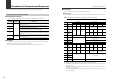
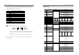
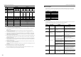
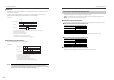
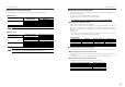
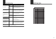

Table Of Contents
11
Parameters of Commands and Responses
*5 The data number “008” can be read to check the error status of the sensor amplifiers.
Convert the five digit number (ASCII characters) read from the sensor amplifiers to a binary
number and check the ON/OFF state of each bit to
check the error contents.
For information on each error, refer to "FD-S Series User's Manual".
•
When the data read from a sensor amplifier is "1056":
"1056" converted to binary number is "0000 0100 0010 0000".
Therefore, this data indicates that the "temperature low error" and the "reverse
current error" have occurred at the same time on the sensor amplifier from which the
data was read.
•
If no error has occurred at the sensor amplifier, the data "0000" is returned.
*6 When the data falls below 0, this indicates "-999.9", and when the data exceeds 99.9, this
indicates "+999.9".
Bit Error contents of sensor amplifiers
0 Not used
1 Head connection error (ErH)
2 Overcurrent error (ErC)
3 EEPROM error (ErE)
4 Empty pipe error (Erd)
5 Reverse current error (rEv)
6 Not used
7 Not used
8 Not used
9 Drive gain error
10 Temperature low error
11 Temperature high error
12 to 15 Not used
Reference
Bit 10: Temperature low error Bit 5: Reverse current error
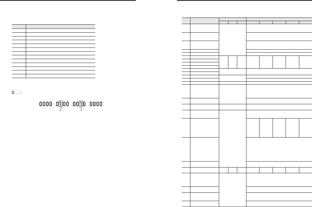
Parameters of Commands and Responses
● Read/write data
The following table lists the types of data that can be read from and written to FD-S Series sensor amplifiers.
Data
number
Data name
Data format
*1
Data range
0.2L 1L, 2L 8L, 20L 0.2L 1L 2L 8L 20L
020 Integrated flow reset request
*
0: Disable integrated flow reset
*3
1: Integrated flow reset
Lead: Last written value
021
Instantaneous flow hold value
reset request
0: Disable hold reset
*3
1: Hold reset
Lead: Last written value
022
Temperature hold value reset
request
0: Disable temperature hold reset
*3
1: Temperature hold reset
Lead: Last written value
023 Zero adjustment request 0o1: Perform zero adjustment
*4
024 Request initial reset (SLct) 0o1: Conduct initial reset (SLct)
030
Instantaneous flow rate setting 1
***.* **** **.**
000.0 to
400.0
*5
0000 to
2000
*5
0000 to
4000
*5
00.00 to
16.00
*5
00.00 to
40.00
*5
031
Instantaneous flow rate setting 2
032
Instantaneous flow rate setting 3
033
Instantaneous flow rate setting 4
034
Integrated flow quantity setting 1
**** 0000 to 9999
035
Integrated flow quantity setting 2
036 Temperature setting lower limit
***.*
000.0 to 099.9
*6
037
Temperature setting upper limit
000.1 to 100.0
*7
038
Specified density for voL.S
**** 0300 to 2000
040 Detection mode
*
0: F-1
1: F-2
2: F-3
3: A-1
4: A-2
041 Integration direction
0: Increment
1: Decrement
042
Time-out time for output 2
(unit: s)
** 1 to 99
043 Output mode
*
Bit0: Output1 (1: N.C.)
Bit1: Output2 (1: N.C.)
Bit2: Output3 (1: N.C.)
044
Integrated flow quantity unit
(Original Method)
1: 0.1
2: 1
3: 10
4: 100
5: 1000
7: (1L(Foc) is
fixed to 7)
7: Fixed
2: 1
3: 10
4: 100
5: 1000
6: 10000
7: (8L(Foc) is
fixed to 7)
7: Fixed
0: 0.01
1: 0.1
2: 1
3: 10
4: 100
045 Response time
0: 0.05s
1: 0.1s
2: 0.5s
3: 1.0s
4: 2.5s
5: 5.0s
6: 10.0s
7: 30.0s
8: 60.0s
046 Display mode
0: Std
1: rESo
047 Hysteresis ***.* **** **.**
000.0 to
200.0
0000 to 1000 0000 to 2000
00.00 to
08.00
00.00 to
20.00
048
Input terminal function
*
0: OFF
1: Bank switching
2: Flow rate zero
3: Zero adjustment
4: Integration reset
049
Flow indicator color (Can set
at 1L or 8L, however ignore)
0: Red for ON, green for OFF
1: Green for ON, red for OFF
050
Power save mode
0: OFF
1: ON
2: FULL
051
Analog output selection
0: Standard
1: Free range analog