
Instruction Manual


17
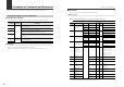
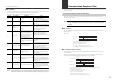
Troubleshooting
Problem Cause Action
The power indicator (POWER)
does not light up.
Power is not
supplied.
Make sure that the voltage of the power supplied to the
sensor amplifier main unit is 20 to 30 VDC.
DL-RS1A is not
properly inserted to
the expansion
connector of the
sensor amplifier.
Reconnect the unit following the instructions in "Connecting
the Unit to Sensor Amplifiers" (page 3).
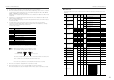
The alarm indicator lights up
before communication starts.
DL-RS1A is
connected to a
sensor amplifier that
does not support DL-
RS1A.
Make sure that the unit is connected to an appropriate
sensor amplifier model (refer to "Available sensor amplifiers"
(page 4)).Reconnect the unit following the instructions in
"Connecting the Unit to Sensor Amplifiers" (page 3).
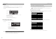
The communication status
indicator (RD) of DL-RS1A does
not flash when you send a
command from an external
device.
The RD terminal of
DL-RS1A is not
connected to the
SD terminal of the
external device.
Check the connection wiring by referring to "Connecting the
Unit to External Devices" (page 5).
No communication
data is sent from the
external device.
Make sure that communication commands are sent out from
the external device.
The alarm indicator lights up
while data is transmitted.
Communication
settings are
incorrect.
Make sure that DL-RS1A and the external device have the
same settings specified for communication speed, data bit
length, and parity check.
For information on configuring DL-RS1A, refer to "Part
Names and Functions" (page 2).
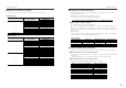
The communication status
indicator (RD) of DL-RS1A
flashes but the communication
status indicator (SD) does not
flash while data is transmitted.
The communication status
indicator (SD) of DL-RS1A
flashes while data is
transmitted, but the data cannot
be retrieved by an external
device.
Proper
communication is
not established.
Lower the communication speed. Use a shielded cable for
the communication cable (refer to "Connecting the Unit to
External Devices" (page 5)). Modify the connection wiring so
that noise does not enter the communication cable.
A communication error
response is returned from DL-
RS1A while data is transmitted.
For the cause and action, refer to page 13.
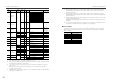
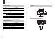
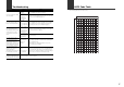
ASCII Code Table
The following table lists the ASCII codes.
0
0
1
2
3
4
5
6
7
8
9
A
B
C
D
E
F
123456789
S
P
N
U
L
D
L
E
D
C
1
D
C
2
D
C
3
D
C
4
N
A
K
S
Y
N
E
T
B
C
A
N
S
U
B
E
S
C
S
O
H
S
T
X
E
T
X
E
O
T
E
N
Q
A
C
K
B
E
L
B
S
E
M
H
T
L
F
V
T
F
F
C
R
S
O
D
E
L
S
I
0 @ P ` p
High-order 4 bits
! 1AQaq
” 2BRb r
# 3CScs
$ 4DTd t
% 5EUeu
& 6FVf v
’ 7
Low-order 4 bits
GWg w
( 8HXhx
) 9IYiy
: JZ j z
+; K [ k {
,< L\ l|
ー=M ] m }
.> N ^ n
~
/
→
←
↑
↓ ?O_ o