
Instruction Manual


12
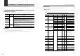
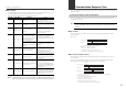
Parameters of Commands and Responses
*1 In the Data format column, "*" signifies a number from "0 to 9".
*2 Indicates that the data can only be read from (R), can only be written to (W), or can be both read
from and written to (R/W) the sensor amplifiers.
*3 Since each reset request is a level action, resets are continuously performed as long as the
value is set to 1.
Make sure you send a command format that writes 0 to the sensor amplifiers again after
receiving a response format.
*4 Regardless of the display mode specified on the sensor amplifiers, the range of configurable data
is the same as the "rESo" mode.
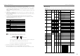
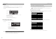
044
Integrated flow
quantity unit
-
*1R/W
2
045 Response time
*1R/W
0: 0.5
1: 1
2: 2.5
3: 5
4: 10
5: 30
6: 60
3
046 Display mode
*1R/W
0: Std
1: rESo
FD-MH10: 0
FD-MH50: 1
FD-MH100: 1
FD-MH500: 0
047 Hysteresis
FD-MH10 *.** 4
R/W
0.00 to 9.99
*4
0.10
FD-MH50 **.* 4
00.0 to 49.9
*4
00.5
FD-MH100 **.* 4
00.0 to 99.9
*4
01.0
FD-MH500 ***.* 5
000.0 to 499.9
*4
005.0
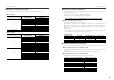
048
Bank switching
function
-
*1R/W
0: OFF
1: ON
0
049
Flow indicator color
*1R/W
0: Red for ON, green for OFF
1: Green for ON, red for OFF
1
050 Power save mode
*1R/W
0: Do not use
1: Use
0
051
Analog output
selection
*1R/W
0: Standard
1: Free range analog
0
052
*7
Free range
analog lower limit
FD-MH10 ** 2
R/W
00 to 20 (Configurable unit: 1) 00
FD-MH50 *** 3
000 to 100 (Configurable unit: 5) 000
FD-MH100 *** 3
000 to 200 (Configurable unit: 10) 000
FD-MH500 **** 4
0000 to 1000 (Configurable unit: 50) 0000
053
*7
Free range
analog upper limit
FD-MH10 ** 2
R/W
00 to 20 (Configurable unit: 1) 10
FD-MH50 *** 3
000 to 100 (Configurable unit: 5) 050
FD-MH100 *** 3
000 to 200 (Configurable unit: 10) 100
FD-MH500 **** 4
0000 to 1000 (Configurable unit: 50) 0500
054 Keylock function
-
*1R/W
0: Unlock
1: Locked
0
060
Factory reset
(initialization)
*1
R 0 - 1: Last written value
0
W
0 o 1: Perform initial reset
*8
Data
No.
Data name
Sensor
head
Data
format
*1
No. of
bytes
Attribute
*2
Data range
Initial value
Data FD-MH10 FD-MH50 FD-MH100 FD-MH500
00.01
Cannot be set Cannot be set Cannot be set
1 0.1 0.1 0.1
Cannot be set
21 1 1 1
310 10 10 10
4 100 100 100 100
5
Cannot be set
1000 1000 1000
6
Cannot be set Cannot be set Cannot be set
10000
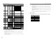
Parameters of Commands and Responses
*5 When setting this value to 000.0, no alarm output is made even if the temperature falls below the
indicated temperature setting lower limit; an alarm output is made only when the temperature
exceeds the upper limit.
*6 When setting this value to 100.0, no alarm output is made even if the temperature exceeds the
indicated temperature setting upper limit; an alarm output is made only when the temperature falls
below the lower limit.
*7 To read or write this data type, the analog output of the sensor amplifiers must be set to "Free range
analog" (using data number 051).
Changing the Free range analog upper limit/lower limit is invalid when the analog output is set to
"Standard".
*8 The command is executed only when the setting of the sensor amplifiers is changed from 0 to 1. To
re-execute the command, first change the setting to 0, then change it to 1.
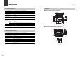
■ Control outputs
This parameter is used with communication command "MS" and DRQ input. Specify the ON/OFF
state of the control output, integrated pulse output, and error alarm output using a one-digit value
(ASCII character).
Data Description
0 Outputs 1, 2, 3 OFF
1 Output 1 ON, 2 OFF, 3 OFF
2 Output 1 OFF, 2 ON, 3 OFF
3 Output 1 ON, 2 ON, 3 OFF
4 Output 1 OFF, 2 OFF, 3 ON
5 Output 1 ON, 2 OFF, 3 ON
6 Output 1 OFF, 2 ON, 3 ON
7 Outputs 1, 2, 3 ON