B3000 SERVICE MANUAL 60-200807-000, REV C
Thank you for your purchase of the B3000 Keurig Single Cup Brewing System! U U The B3000 is the ultimate in Keurig Brewed ® technology! The brewer features four brew sizes and a unique, easy to use, user LCD interface. The B3000 is engineered to provide many years of uninterrupted service to your customers. The B3000 is also a highly serviceable brewer. It is built in a modular fashion which makes it easy to perform preventative maintenance and service should the need arise.
B3000 Service Manual Table of Contents I. Operation 1. B3000 Brewer Overview, Brewer Schematic / Schematic Legend 2. Brewer External Components 3. The Keurig K-Cup® Portion Pack 4. Appliance Safety 5. Brewer Setup 6. User Interface & Brewing Procedure 7. Menu Mode Below Serial Number 7505 8. Menu Mode Above Serial Number 7506 9. Draining the Brewer 10. Emptying the K-Cup Bin Page 5 10 12 13 13 15 19 22 26 27 II. Construction 1. The Modules a. Power b. Puncture Mechanism c. Hot Water Tank d.
5. De-Scaling Procedure 6. Sanitizing / Cleaning Puncture Mechanism 62 64 IV. Product Warranty Information 69 V. Certifications and Specifications 71 VI. Accessories Appendix 1. Water Filter 2. Coin Changer Accessory 3. Platform Unit VII. BIT Testing Brewers 1- 7505 Brewers 7506 and above VIII.
I. Operation 1. Brewer Overview U The Keurig B3000 Brewer is a commercial single serve coffee brewer specifically designed to be used with the proprietary Keurig K-Cup® portion pack. Coffee beans or ground coffee cannot be processed in this brewer. It can be configured with a coin vend control unit and a platform cabinet for additional K-Cup disposal capacity. It consists of a dual water tank capacity system which allows for fast sequential brewing.
B3000 Brewer Water Flow Mechanisms A schematic and legend showing the major components of the B3000 are provided (refer to page 8 and 9). The functions of these components are listed below. 1. Water filling – The B3000 is a direct plumbed machine. Municipal water is introduced to the unit through the inlet valve [X]. The supply water is then led to the cold water tank [BB] via the rigid plastic tube connected to the float valve [Y].
5. Dispensing Hot Water - To deliver hot water only, the system is closed, vent valve [J] is deenergized, and the hot water dispense valve [OO] is opened. Through a combination of the force of gravity and a pressure boost from the brew pump, water now flows from the lower hot water tank cover thru a silicone tube, the hot water dispense valve [OO], a silicone o-ring, seal cover, and the hot water trough.
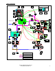
U Brewer Schematic Rear Power Panel G JJ B C PP E CC D HH GG H M X System Control Inlet Water Supply DD A K L N O J U TB MM P Y LL AA V Q Z OO BB R NN S M KK EE U TP W V Q R FF System Inputs S System Outputs Cold/Hot Water Plumbing Air Plumbing B3000 SERVICE MANUAL 60-200807-000, REV C 8
BREWER SCHEMATIC LEGEND A Electronics, 3 PCBAs The Processor: B3000 I/O Overview B LCD User Interface D Pressure Transducer E Puncture mech. Switch G Brew Pump H K 4 Brew Vol Conduct. Probes N Q C 4 Push buttons / LEDs Filter Tee J Vent Valve L Brew Tube M Check Valves (3) Entrance Needle O K-Cup® Portion Pack P Exit Needle Auto reset TCOs (2) R Heating Elements (2) S Baffles (2) Hot Water Tanks.
2.
WATER FILTER BRACKET WATER FILTER HEAD, KQ8A WATER FILTER CARTRIDGE, KQ8A ⅜” or ¼” DIAMETER TUBING (FROM WATER SUPPLY) (FROM FILTER TO INLET VALVE) PUNCTURE HANDLE ROTATED BACK WITH PUNCTURE MECHANISM IN OPEN POSITION K-CUP K-CUP HOLDER B3000 SERVICE MANUAL 60-200807-000, REV C 11
3. The Keurig K-Cup® Portion Pack The Keurig B3000 Brewer may only be utilized in conjunction with the single serve portion pack called the Keurig K-Cup. The K-Cup is fitted with a paper filter that is heat sealed to the inside upper edge of the plastic cup. Depending on the individual blend, up to approximately 9 to 14 grams of premium freshly ground coffee is added. The K-Cup is nitrogen purged to remove oxygen and heat sealed with a three ply foil lid to lock in freshness for at least 6 months.
4. Appliance Safety When using electrical appliances, basic safety precautions must always be followed. Read all instructions before using this brewer. Failure to comply with the instructions risks equipment damage, fire or severe bodily injury. WARNING: ALWAYS UNPLUG THE BREWER BEFORE SERVICING • To reduce the risk of fire or electric shock, do not expose this brewer to rain or moisture. • Do not immerse the brewer in water, as this could lead to electric shock, electrical and or mechanical malfunctions.
Filter Requirements The Keurig B3000 brewer system requires the use of a water filtration system to optimize the coffee flavor and brewer reliability. Two mounting holes with screws have been provided on the back of the brewer for this purpose. Keurig recommends the Omnipure KQ8A filter. A filter kit (part number 5025) is available from Keurig. This kit contains a KQ8A filter, filter head, and mounting bracket. NOTE: NO PLUMBING CONNECTORS ARE PROVIDED WITH THIS KIT.
6. User Interface & Brewing Procedure (Without a coin changer) IMPORTANT: The brewer must be primed for its first use as set forth below. If Spanish or French are going to be the primary language, then you must go to the MENU MODE (page 19) and change the language before proceeding with the priming of the brewer. The brewer’s default language is English. - NOTE: The B3000 power switch uses “0” for OFF and “ ” for ON. Priming the Brewer 1.
Ready to Brew your First Cup (Without Coin Changer) 1. When the LCD displays the above information, the brewer is ready for use. 2. Select a K-Cup portion pack. NOTE: Do not remove the foil lid or puncture the K-Cup portion pack. 3. Lift the puncture mechanism handle. The K-Cup holder will open towards you. CAUTION: There are two sharp needles that puncture the K-Cup portion pack, one in the puncturing mechanism and the other in the bottom of the K-Cup holder.
6. Place a cup or mug on the Cup/Drip Tray plate. 7. The LCD screen will display the image below. A choice of 4, 6, 8, and 10 oz cup sizes are available. Make cup size selection at this time. 8. After the selection is made, the image below will display which cup size is brewing by having the respective button corresponding to the volume size being illuminated. CAUTION: There is extremely hot water in the K-Cup holder during the brew process.
9. At the end of the brewing process the image below will be displayed for 4 seconds. 10. There may be a short pause (approximately 20 seconds) before the next brewing process can begin. The entire brew process lasts for approximately 40 to 52 seconds (depending upon brew size selected) and ends with a burst of air to remove all liquid coffee or tea from the K-Cup. 11.
7. Menu Mode (For brewers with serial numbers 1 thru 7505) The Menu Mode allows you to: • Set the language to be displayed. • See the number of brew cycles that the brewer has completed. • Prime after draining. • Set the brewer to vend / no vend. • Set pricing. • Adjust the brew temperature between 192 and 187 degrees F (89 and 86 degrees C). • Invert the background text color display intensity. • List your telephone service number. (Scroll and set all ten digits, using the NEXT and ADJUST buttons).
2. Press the ‘Next’ button. 3. The display will look like this (number of brews): 4. Press the ‘Next’ button. 5. The display will look like this (was brewer drained): 6. Press the ‘Yes’ or ‘No’ button as appropriate. 7. The display will look like this (set vend / no vend): 8. If a coin unit is being used, Press ‘Adjust’ button to ‘Vend at Set the price’ (image on left below).
9. The display will look like the image on the right below. Adjust price by pressing the + or – button to get desired price. Adjustments are in $0.05 increments. 10. Press the ‘Next’ button after selection is made. 11. The next display will read ‘Set the Brew Temp’ at the display continue to press the next button until the following display is seen, and then the brewer and coin changer unit are ready for operation. NOTE: YOU MUST SCROLL THROUGH THE MENU MODE COMPLETELY.
8. Menu Mode (For brewers with serial numbers 7506 and above) The Menu Mode allows you to: • Set the language to be displayed. • See the number of brew cycles that the brewer has completed. • Set the brewer to vend / no vend. • Set pricing. • Adjust the brew temperature between 192 and 187°F (89 and 86 degrees C). • Invert the background text color display intensity. • List your telephone service number. (Scroll and set all ten digits, using the NEXT and ADJUST buttons). • Turn ON / OFF Mug Light.
1. Once the menu is accessed the display will look like this (set language): 2. Press the ‘Next’ button. 3. The display will look like this (number of brews): 4. Press the ‘Next’ button. 5. The display will look like this (set vend / no vend): 6. If a coin unit is being used, Press ‘Adjust’ button to ‘Vend at Set the price’. Then press next button. 7.
8. Adjust price by pressing the + or – button to get desired price. Adjustments are in $0.05 increments. 9. Press the ‘Next’ button after desired amount has been set. 10. The next display will look like these (set the brew temp). The temperature can be adjusted in one degree increments between 187 – 192 °F by pressing the “Adjust” button. 11. The next screen will look like these (invert display colors). You can changes the display to LIGHT back ground with DARK letters by pressing the “Adjust” button. 12.
14. The next screen will look like this (hot water dispense). You can disable the plain Hot Water button by pressing the “Adjust” button. 15. The next screen will look like this (select cup sizes). You can select which cup sizes you want the brewer to dispense. You can disable up to 3 cup sizes. One cup size has to be on. 16. The next screen will look like this (error code). The last error condition that the brewer detected will be display in this menu.
9. Draining the Brewer When you wish to drain the brewer, the following steps must be followed: 1. Press the power button to the “0” position and unplug power cord. 2. Shut off water and disconnect water supply to the brewer. Turn the brewer around so the back is facing you. 3. Move the brewer close to the edge of a sink or large bucket so that the drain hoses hang over either the sink edge or into the bucket 4. Remove both the Hot Water and Cold Water hoses from their clips.
10. Emptying the K-Cup Bin The used K-Cups are automatically ejected into the internal K-Cup bin. When the K-Cup bin requires emptying, the brewer will display: EMPTY K-CUP BIN To empty the K-Cup bin, open the brewer door by grasping the door handle and swinging door fully open to remove bin from brewer. Dispose of the used K-Cups and reinstall the bin. The bin will ONLY go back inside the brewer one way.
II. Construction 1. The Modules What follows are images of the individual modules to show their general configuration. Not all of the parts in the module are listed. A. Power – located at lower rear of brewer: POWER CORD DRAIN TUBES FUSE HOLDER COLD WATER TANK DRAIN TUBE WATER PUMP MANIFOLD HOT WATER TANK HARNESS COIN CHANGER CONNECTION INLET VALVE TUBE CONNECTOR (CWT) B.
C. Hot Water Tank – located at the left rear of brewer: BREW TANK COVER HWT MOUNTING BACK CONNECTORS HWT MOUNTING FRONT D.
E. Cold Water Pump – located at the lower right rear of brewer: COLD WATER PUMPS PLATE VIBRATION ISOLATORS F.
G. FRONT DOOR – located on the front of brewer: CUP PLACEMENT LED SENSORS CUP/DRIP TRAY LOCATION DOOR HANDLE H. BIN FULL SENSOR - located on the left/right side of brewer: BIN FULL SENSORS I.
J.
2. REPLACEMENT PART NUMBERS POWER MODULE K-CUP PUNCTURE MODULE HOT WATER TANK MODULE COLD WATER TANK MODULE COLD WATER PUMP MODULE CONTROL PANEL MODULE FRONT DOOR MODULE MAIN HARNESS MODULE BIN SENSOR MODULE (Included in Main Harness Module) DRIP TRAY MODULE MAIN PCB MODULE HOT WATER DISPENSE VALVE ASSEMBLY K-CUP HOLDER ASSEMBLY INLET VALVE FILTER LOCKSET COIN MECH B3000 CHUTE B3000 INLET WATER VALVE B3000 DISPOSAL BIN BASE PLATE MODULE CLAMP, HOSE, 14.81MM ID x 7.92MMW, SPRING STL CLAMP, HOSE, 9.
III. Servicing 1. Preventive Maintenance Regular cleaning of the Brewer’s external components is recommended. CAUTION: Never immerse the base unit in water or other liquids. The brewer’s enclosure and other external components may be cleaned with a non-toxic food grade cleaner and a damp, non-abrasive cloth. • The Drip Tray and Drip Tray Plate should be periodically inspected and rinsed clean. • The K-Cup Bin should be cleaned on a regular basis.
3. Diagnostics – Error Codes: The B3000 contains real-time error detection. There are a number of operational errors that, if encountered, will disable the brewer, produce an error code onto the LCD display, and will also flash all 4 buttons on the front panel LED’s to attract attention. The power may be cycled to attempt to clear the error, but if it occurs again, the same message will be displayed. Below is a summary of all errors, their meanings and the menu messages.
4. Removing/Installing Modules The B3000 brewing system is modular in design. This design facilitates ease of repair at customer locations. There are no component level repair capabilities for this brewer. The following describes the removal of each of the modules. NOTE: BOTH THE HOT AND COLD WATER TANKS MUST BE DRAINED AND THE UNIT UN-PLUGGED BEFORE ANY MODULE IS REMOVED. A.
B. POWER MODULE (Located in the back on the bottom edge of the brewer) See REMOVAL of OUTER PANELS (page 36). After completion of panel removal, the technician must attach an ESD wrist strap to themselves and the metal base plate of the brewer. Spare Fuse Location 1. Completely loosen the two captive screws holding the Power Module to the bottom base plate and pull out slightly. This will help in accessing the hoses on the pumps. 2.
3. Disconnect the clamps and water hoses attached to the water manifold. 4. Disconnect the Multi Connector Tee manifold from the old Power Module and add to the replacement unit. 5. Disconnect the Cold Water drain tube from the bottom of the tank.
6. Disconnect the tube from the Inlet Valve that goes to the Cold Water Tank. The Inlet Valve is located on the Power Module. This is a quick release tube connection. Remove the black locking clip from the fitting if present. Push in on the collar, and pull out the tube. 7. Disconnect the wire harness attached to the Hot Water Tank module. Looking at the left side of the brewer when facing from the front, locate the main power harness, and transformer. 8.
10. Install the new module and connect all of the appropriate connections, hoses, and wires making sure that they are secure and tight. 11. Conduct a BIT test (see appendix VII on page 85) to insure the proper function of the brewer. NOTE: There is a removable filter screen located in the Inlet Valve. If this screen should become blocked by foreign material preventing water from flowing into the brewer, you can gently remove the blocked screen using a pair of needle nose pliers and insert a new one.
C. PUNCTURE MECHANISM MODULE (Located in the top front portion of the brewer) See REMOVAL of OUTER PANELS (page 36). After completion of panel removal, the technician must attach an ESD wrist strap to themselves and the metal base plate of the brewer. 1. Disconnect the Hot Water Valve tube from the top of the Bottom Hot water tank. This hose is on the right hand side of the brewer looking at the front of the brewer. Looking at the front of the brewer, BREWERS ≤ 7505 BREWERS ≥ 7506 2.
5. Release the hose clamp and remove the brew tube from the entrance needle assembly. 6. Loosen the four screws that hold the puncture module in place. There are two on each side. They are captive screws so they will NOT come out completely. Looking toward the back of the Puncture Mechanism Module area 7. Lift the Puncture Mechanism Module straight up about 2 inches (50mm) to disengage the unit from a support mount. Support the module with your hand.
8. Disconnect the multi colored wire harness located to the left of the Hot Water Valve and the two wires on the Hot Water Valve solenoid. There is no polarity for these wires. 9. Disconnect the Vent tube from the venting nipple on the left hand side of the module area. 10. The Puncture Mechanism Module can now be removed from the brewer.
D. HOT WATER VALVE ASSEMBLY (Located at the back of the Puncture Mechanism) See REMOVAL of OUTER PANELS (page 36). After completion of panel removal, the technician must attach an ESD wrist strap to themselves and the metal base plate of the brewer. See REMOVAL of PUNCTURE MECHANISM (page 41). 1. Locate the Hot Water Valve on the back of the Puncture Mechanism. 2. Remove the two self tapping Phillips screws. 3. Loosen the large plastic nut at the bottom of the valve assembly.
4. Gently pull OUT and UP the valve assembly. 5. Reinstall the new valve. NOTE: When reinstalling the new valve, you MUST make sure that the “O” ring on the bottom of the outlet tube is in place. NOTE: The large Plastic Nut must be tight. Failure to do so will cause a leak when the hot water feature is selected. 6. Conduct a BIT test (see appendix VII on page 85) to insure the proper function of the brewer.
E. HOT WATER TANK MODULE (Located in the back right side of brewer) See REMOVAL of OUTER PANELS (page 36). After completion of panel removal, the technician must attach an ESD wrist strap to themselves and the metal base plate of the brewer. NOTE: Before disconnecting the two hoses on top of the module, make a note of where they are attached. The LEFT hose comes from the Cold Water Tank. The RIGHT hose goes to the Puncture Mechanism Module. These hoses MUST be reinstalled correctly.
3. Disconnect the Hot Water Valve hose from the top of the bottom tank. 4. Locate the two screws at the top of the module. Loosen them fully. These are captive screws so they will NOT come out completely. 5. Tilt the module toward you. It is secured on the bottom with mounting tabs. Lift the module out carefully.
6. Remove the nut (6mm) securing the green ground wire on the left hand side of the Power Module. 7. Disconnect the hose from the bottom tank. 8. The Hot Water Tank Module can be removed from the brewer. 9. Install the new module and connect all of the appropriate connections, hoses, and wires making sure that they are secure and tight. 10. Conduct a BIT test (see appendix VII on page 85) to insure the proper function of the brewer.
F. COLD WATER TANK MODULE (Located at the top right of the brewer) See REMOVAL of OUTER PANELS (page 36). After completion of panel removal, the technician must attach an ESD wrist strap to themselves and the metal base plate of the brewer. Looking at the right side of the brewer, take note of the cutout in the chassis near the top. You will see one small hose and two larger ones. 1. Disconnect the small hose from the filter tee, just above the vent valve. 2. Disconnect the larger hose on the right. 3.
4. Remove RED retaining clip from Murdock fitting. This is a quick release tube connection. Push in on the collar, and pull out the tube. 5. Release clamp and disconnect the hose on the LEFT side of the top Hot Water Tank. 6. Disconnect the hoses on the top of each of the water pumps. 7. Disconnect the Cold Water Tank drain hose on the bottom right side of the tank.
8. Loosen fully the two screws that secure the Cold Water Tank to the chassis. They are captive screws so they will NOT come out completely. 9. While gently holding the plastic tube from the Inlet Valve out of the way, remove the Cold Water Module. 10. Install the new module; connect all of the appropriate connections, hoses and wires making sure that they are secure and tight. 11. Conduct a BIT test (see appendix VII on page 85) to insure the proper function of the brewer.
G. COLD WATER PUMP MODULE (Located in the middle of the brewer) See REMOVAL of OUTER PANELS (page 36). After completion of panel removal, the technician must attach an ESD wrist strap to themselves and the metal base plate of the brewer. Looking at the rear, in the middle of the brewer you will see the Cold Water Pump module. 1. Disconnect the hose on the top of each pump, two places. 2.
NOTE: The wires must be reconnected to their proper connections when installing the new module. Failure to do so will result in having extremely noisy pumps while they are in operation. Make sure that Cold Water Tank drain hose is NOT pinched when reassembling. 3. Disconnect these four wires. 4. Loosen the captive screws holding the Power Module in place. (page 36) Gently slide out the module. This will allow access to the manifold clips. 5.
H. CONTROL PANEL MODULE (Located on the left front of the brewer) CAUTION: The technician must attach an ESD wrist strap to themselves and the metal base plate of the brewer or earth ground when replacing this module. 1. Open the K-Cup Bin door. 2. Tip the brewer back slightly and locate the two screws under the Control Panel. Remove these screws completely. 3. Gently pull out and up on the module to remove from the brewer. 4.
5. Disconnect the small tube at the union connection. 6. Disconnect the wire harness connection. 7. The Control Panel Module can now be removed. 8. Install the new module and connect all of the appropriate connections, hoses, and wires making sure that they are secure and tight. 9. Conduct a BIT test (see appendix VII on page 85) to insure the proper function of the brewer.
I. FRONT DOOR MODULE (Located at the bottom of the brewer in the front). NOTE: To remove the Front Door Module you MUST first remove the Control Module screws and gently push the module up from the chassis to allow the TOP hinge pin to be removed. You do not need to remove the Control Module or disconnect any connections. 1. Open the K-Cup bin door. Locate the wire harness cover plate and the three screws that secure this cover 2. Remove the screws and cover plate. 3.
5. Locate the two hinge pins connecting the door to the brewer. 6. Using a flat screw driver, gently pry the hinge pins up and out. 7. Carefully pull the wire harness through the opening. 8. The Door Module can now be removed. 9. Install the new module and connect the appropriate wire connection, cover plate and reinsert the hinge pins making sure that they are secure and tight. 10. Conduct a BIT test (see appendix VII on page 85) to insure the proper function of the brewer.
J. MAIN PCB MODULE (Located on the Left side of the brewer) See REMOVAL of OUTER PANELS (page 36). After completion of panel removal, the technician must attach an ESD wrist strap to themselves and the metal base plate of the brewer. 1. Remove the plastic bar in front of the Main PCB and disconnect the three wire harness connections on the board. 2. Remove the four screws holding the PCB to the chassis. Set the PCB aside. 3. The Main PCB can now be removed. 4.
K. BIN FULL SENSORS (Located on each side of the of the K-Cup bin cavity) See REMOVAL of OUTER PANELS (page 36). After completion of panel removal, the technician must attach an ESD wrist strap to themselves and the metal base plate of the brewer. See REMOVAL of MAIN PCB MODULE (page 58). After completion of PCB removal: To remove the LEFT side LED, as you face the brewer. 1. Remove the screw holding the LEFT LED in place. 2. Disconnect the bin sensor.
4. This completes the LEFT side bin sensor removal. Install the replacement sensor, the main PCB, and plastic bar. Make sure that all connections are tight. To remove the RIGHT side bin sensor 1. Remove the screw holding the RIGHT LED in place. Looking at the front of the brewer, BREWERS ≤7505 BREWERS ≥ 7506 2. Raise the Puncture Mechanism handle and locate the two screws that hold the puncture cover in place. 3. Remove these screws. 4. Push the cover back slightly and lift up to remove.
5. Disconnect the SMALL connector toward the back of the Puncture Mechanism module area. If it is easier, you can remove the Puncture Mechanism Module completely to gain access to this connector. 6. Carefully pull the wire through the opening in the chassis and remove the RIGHT side bin sensor. 7. This completes the RIGHT side bin sensor removal. Install the replacement sensor making sure that all connections are tight. Attach the Puncture Mechanism Module cover and tighten its retaining screws. 8.
De-Scaling Your Brewer Mineral content in water varies from place to place. Depending on the mineral content of the water in your area, calcium deposits or scale may build up in your brewer. Scale is nontoxic, but left unattended, it can hinder brewer performance. De-scaling your brewer helps maintain the heating element and other internal parts of the brewer that come in contact with water. The brewer should be de-scaled every 6 months to ensure optimal performance.
5. Power off the brewer and drain both hot and cold water tanks. 6. Reconnect the brewer to the filtered cold water supply and follow the PRIME procedure to refill the brewer. 7. Once the prime process is complete, power off the brewer and drain both hot and cold water tanks again. 8. Power up the brewer and follow the PRIME procedure again, performing several (10) cleansing brews to remove any residual taste from the citric acid.
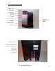
6. Sanitizing / Cleaning the Puncture Mechanism (P.M.) FOR PROPER SANITIZING / CLEANING OF THE PUNCTURE MECHANISM, THE FOLLOWING ITEMS ARE RECOMMENDED. A A. DISHWASHING LIQUID SOLUTION OR SOAP & WATER IN A SPRAY BOTTLE. B. MINI SCRUB BRUSH FOR CRAMPED AND TIGHT AREAS [i.e. AS SHOWN, McMASTERCARR PT NO. 7243T22]. B C C. CLOTH FOR WIPING. D. ACCESS TO A SINK (IDEALLY WITH FRUIT SPRAYER) OR A BUCKET OF WATER FOR RINSING. SEE IMAGES 18 AND 19. A. Sanitizing/Cleaning the B3000 Inlet Needle and Gasket 1.
B. Sanitizing/Cleaning the Puncture Mechanism (P.M.) 1. P.M. REMOVED AS DESCRIBED IN THIS MANUAL. 4. TO REMOVE THE BOTTOM P.M. COVER, REMOVE THE THREE SCREWS INDICATED ABOVE. 2. REMOVE LOWER P.M. COVER BY REMOVING THE TWO SCREWS AS INDICATED ABOVE. 5. HERE THE P.M. IS SHOWN WITH THE BOTTOM P.M.COVER REMOVED. B3000 SERVICE MANUAL 60-200807-000, REV C 3. HERE THE P.M. IS SHOWN WITH THE LOWER P.M. COVER REMOVED. 6.
7. THE MODULE FRAME SHOULD BE SPRAYED WITH A SOAPY SOLUTION OR MILD DETERGENT. 8. THE MODULE CAN BE MANEUVERED SO ALL AREAS CAN BE REACHED BY THE SPRAY. 10. USE THE DETAILING END OF THE BRUSH TO REACH INSIDE THE MODULE FRAME TO REMOVE DEBRIS. 11. A CLOTH CAN BE USED TO WIPE THE FRAME CLEAN AND TO DRY IT AFTER RINSING UNDER A FAUCET, OR RINSING WITH A FRUIT SPRAYER, OR RINSING IN A BUCKET OF WATER. B3000 SERVICE MANUAL 60-200807-000, REV C 9. USE SMALL SCRUB BRUSH TO REMOVE DEBRIS FROM THE MODULE. 12.
13. USE THE SCRUB BRUSH ON THE UNDER COVER AS NECESSARY. 16. BRUSH PART AS NECESSARY. 14. USE A CLOTH WIPE AS REQUIRED. RINSE UNDER FAUCET OR IN BUCKET OF WATER. 17. WIPE THE PART WITH A CLOTH AS NECESSARY. RIINSE UNDER FAUCET OR IN A BUCKET OF WATER. B3000 SERVICE MANUAL 60-200807-000, REV C 15. PREP THE LOWER P.M. COVER WITH CLEANING SPRAY. 18. RINSE FRAME IN BUCKET OF WATER IF AVAILABLE, TAKING CARE NOT TO WET ELECTRICAL COMPONENTS.
19. REMOVE FRAME FROM BUCKET ALLOWING WATER TO DRAIN. 20. MODULE CAN BE PLACED ON TOWEL TO ALLOW FOR FINAL DRAINIG BEFORE WIPING. B3000 SERVICE MANUAL 60-200807-000, REV C 21. RE-ASSEMBLE MODULE TO BE RE-INSTALLED IN BREWER.
IV. Product Warranty Information WARRANTY Set forth below is a summary of warranty information for your Keurig B3000 brewer effective as of the date the Service Manual was printed. The complete details of Keurig’s warranty is set forth in the Non-Exclusive Distributorship Agreement, as amended from time to time, between Keurig and the original purchaser of this Brewer.
OBTAINING WARRANTY SERVICE Keurig Brewers are high quality appliances and, with proper care, are intended to provide years of satisfying performance. However, should the need arise for warranty service, simply call Keurig Field Support at our toll free number 1-888-CUP-BREW (1-888-287-2739). Please do not return your brewer for servicing without first speaking to Keurig Field Support to obtain an Authorization to Return number (ATR).
V. Certifications and Specifications Regulatory Compliance The Keurig B3000 Brewer will comply with: UL 197 Commercial Electric Cooking Appliances ANSI / NSF 25 (applies to brewers F0009546 and higher) Commercial Cooking, Rethermalization, and Powered Hot Food Holding and Transport Equipment. CAN/CSA C22.2 No. 109 – M1981 Commercial Cooking Appliances NAMA Listed National Automatic Merchandising Association Specifications Size………………………………………12 Inches W X 21.3 Inches D X 17.
VI. ACCESSORIES APPENDIX 1. Water Filter Kit (Part Number 5025) Keurig requires the use of a water filtration system for the B3000. The Omnipure KQ8A filter is recommended. This filter has both a Charcoal filter medium for removing chlorine, taste and odor, plus phosphate for the reduction of lime build up inside the brewer. NOTE: The phosphate only slows down the build up of lime. It does not eliminate it. Keurig offers a filter kit for its brewers.
2. Coin Changer Accessory (Part Number 5557) The installation of the B3000 Coin Changer Accessory is covered in the installation guide provided with each coin changer accessory kit. Details for the installation of the changer are provided as an appendix of this manual. If a copy is needed, asked for part number 60-200814-000. Introduction: This guide will detail how to install the coin mechanism that will enable coin operation of the Keurig B3000 Commercial Brewer.
The B3000 Coin Changer Accessory: The B3000 Coin Changer Accessory is custom designed to be used exclusively with the B3000 Commercial Brewer and the aforementioned coin mechanism. All the necessary hardware and cables for assembling the B3000 Coin Changer Accessory are included. See figures 1 and 2. The items included in the accessory kit are: B 1 1. 2. 3. 4. 5. Coin changer cabinet Brewer coin platform High capacity platform Brewer-cabinet plate Accessory package A. Screws 5 ea. B. Control cable C.
2. Join the coin changer cabinet to platform by placing the ‘hooks’ inside the platform slot. See figures 4 and 5 below. DETENTS FOR BREWER FEET Figure 5 Figure 4 Figure 5 3. Place brewer on the platform such that the rubber feet of the brewer fit into the detent areas on the platform and the brewer rests on top of the coin changer cabinet protrusions. See figure 6 below. Figure 6 4. At the rear of the assembled brewer-coin changer cabinet locate the five holes for mounting the Brewer-cabinet plate.
5. Fasten the brewer-cabinet plate to the cabinet (three screws) and to the brewer (two screws). See figures 8 and 9 below. Figure 9 Figure 8 6. Connect the control cable to both RJ11 connectors on the rear of the brewer and the coin changer cabinet. See figure 10 below.
Installing the Coin Mechanism: The step by step procedure for installing the coin changer is as follows: 1. Unlock the coin changer cabinet fascia [Figure 11] and remove it by lifting up at coin retrieval opening [Figure 12]. Remove the top panel of the coin changer cabinet by unscrewing the two screws at the rear of the unit [Figure 13] and sliding the panel rearward and lifting up. Coin retrieval opening Figure 11 Figure 13 Figure 12 2. Mount and connect the coin mechanism.
3. Tightening the Mounting Screws. See Figures 18 and 19 below. The mechanism is shown outside of the coin accessory cabinet. Coin slot Figure 18 Figure 19 To tighten the mounting screws on the Quantum Pro device the upper panel must be opened. To open the panel depress the tab and pull back on the coin slot to rotate the panel toward you and down. Once the panel is rotated down the screws will be exposed for tightening. After tightening rotate the panel up and back until it snaps closed. 4.
Procedure for Setting the Brewer to Coin Operation: Procedure: 1. Attach coin changer unit to brewer per assembly instructions. 2. Connect patch cable to female RJ11 connectors on the back of the B3000 brewer and the coin unit. 3. Plug-in each units cords to outlets. 4. Power both units. Switches are located on the rear bottom of both units. 5. To enable the coin changer unit, access the menu button through the front door of the B3000 brewer.
10. The display will look like this (was brewer drained): 11. Press the ‘Yes’ or ‘No’ button as appropriate. 12. The display will look like this (set vend / no vend): 13. Press ‘Adjust’ button to ‘Vend at Set the price’ (image on left below). Then press next button. 14. The display will look like the image on the right below. Adjust price by pressing the + or – button to get desired price. Adjustments are in $0.05 increments. 15. Press the ‘Next’ button after selection is made.
16. The next display will read ‘Set the Brew Temp’ at the display continue to press the next button until the following display is seen, and then the brewer and coin changer unit are ready for operation. WARNING: The product should be connected to a branch circuit protected at maximum 20A. DANGER: Risk of electric shock. This unit has two power supply cords. Disconnect all power before installing coin or credit mechanism. CAUTION: Risk of Fire or Electric Shock.
3. Platform Unit (Part Number 5558) The assembly of the B3000 Platform accessory is covered in the installation guide provide with each platform kit. Details for the installation of the changer are provided as an appendix of this manual. If a copy is needed, ask for part number 60-200993-000. Platform Chute Storage Bin Fig 1. Contents of the Platform Kit #5558 Lift up the trapdoor in the bottom of the brewer. Fig 2.
Place the Chute in position Fig 3. Install Chute Fig 4.
Fig 5.
VII BIT Testing Manufacturing Built In Test (BIT) The B3000 brewer has the ability of performing diagnostic tests to verify if most of the critical system elements are functioning properly. For brewers from 1 – 7505 see page 85. For brewers 7506 and above see page 89.
TEST TESTS: NO. (TN) 1. Left Button / LED, LCD Pixels mostly on 2. Center Left Button / LED 3. Center Right Button/ LED 4. Right Button / LED 5. Muglight 6. Door Switch (Open) 7. Door Switch (Close) 8. Water Sensor (water level high) 9. Water Sensor (water level low) 10. Mug Sensor (blocked) Mug Sensor (unblocked) Bin Sensor (blocked) Bin Sensor (unblocked) K-Cup® Sensor (blocked) 11. 12. 13. 14.
15. K-Cup® Sensor (unblocked) “15: CLOSE KCUP” “MODULE: BR-HEAD” 16. Brew tank Thermistor @ ambient temperature Pre-heat tank Thermistor @ ambient temperature 120 Hz Clock (60 Hz Power) Heaters off “16: BREW TEMP” “MODULE: HWT” Auto Cont. if OK “17: PREHEAT TEMP” ” MODULE: HWT” Auto Cont. if OK Auto Cont. if OK 17. 18. 20. Brew Tank Heating Element power 21. Preheat Tank Heating Element power 22. Initial Air Pressurization with Water Pump, Pressure transducer 23.
27. HW Dispense valve “27: HWD VALVE” “MODULE: BR-HEAD” 28. Transmit and receive a “1” and “0” through the coin IF 29. Done “29: VEND I/F LOOPBACK” “MODULE: M-PCB, PWR-PANEL” “30: PASS, !!!!” “DONE” Auto Continue if Open VV. Open OK HWDV. Verify HWT <0.1 psi after 2 seconds Auto Continue if OK Power off Stop Test 24 pressurizes the entire hot water part of the brewer, thus checking for leaks in: • All vent line components from the tank through the VV.
Bit Test for brewers 7506 and above TEST NO. TESTS: 1. Left Button / LED, LCD Pixels mostly on 2. Center Left Button / LED 3. Center Right Button/ LED 4. Right Button / LED 5. Mug-light 6. Door Switch (Open) 7. Door Switch (Close) 8. Water Sensor (water level high) 9. Water Sensor (water level low) 10. Mug Sensor (blocked) Mug Sensor (unblocked) Bin Sensor (blocked) Bin Sensor (unblocked) 11. 12. 13.
14. 15. 16. 17. K-Cup Sensor (blocked) K-Cup Sensor (unblocked) 120 Hz Clock (60 Hz Power) PT Sanity check 18. Initial Air Pressurization with Water Pump, Pressure transducer 19. Vent Valve opening under low pressure 20. Full HWT air Pressurization with Brew Pump. Pressure transducer calibration Half CWT Pressurization by sharing; Vent Tubes Vent Valve opening under full over pressure CWT, Vent Tubes Leaks 21. 22. 23. HW Dispense valve 24.
27. Brew Tank Heating Element power 28. Preheat Tank Heating Element power 29. Transmit and receive a “1” and “0” through the coin IF 30.
VIII.