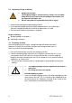
KERN & Sohn GmbH Ziegelei 1 D-72336 Balingen E-Mail: info@kern-sohn.com Phone: +49-[0]7433- 9933-0 Fax: +49-[0]7433-9933-149 Internet: www.kern-sohn.com Installation instructions Drive-through scale KERN KFD V20 Version 1.
GB KERN KFD V20 Version 1.2 10/2013 Installation instructions Drive-through scale Contents 1 2 General ........................................................................................................... 3 Technical data ................................................................................................ 3 2.1 Dimensions ................................................................................................................................. 4 3 4 Appliance overview ........
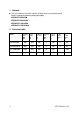
1 General These installation instruction contain all data necessary for placing and commissioning the following weighing bridges: KERN KFD 600V20M KERN KFD 600V20LM KERN KFD 1500V20M KERN KFD 1500V20LM 2 Technical data Model Weighing range Max kg Readability d g Verificati on value e g Minimum load Min kg Preload additive kg Cable length approx. m Net weight approx.
2.
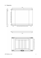
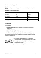
3 Appliance overview 5 Access ramp Weighing bridge Cover of weighing cell feet Connection cable KFD V20-IA-e-1312
4 Basic Information (General) 4.1 Documentation These installation instructions contain all data necessary for placing and commissioning the weighing bridges KERN KFD V20. In combination with a display unit, described below as weighing system, for operation configuration, please refer to the operating instructions of the display unit. 4.2 Proper use The balance you purchased is intended to determine the weighing value of material to be weighed. It is intended to be used as a “non-automatic balance”, i.e.
4.5 Monitoring of Test Resources In the framework of quality assurance the measuring-related properties of the weighing system and, if applicable, the testing weight, must be checked regularly. The responsible user must define a suitable interval as well as type and scope of this test. Information is available on KERN’s home page (www.kern-sohn.com with regard to the monitoring of weighing system test substances and the test weights required for this.
7 Unpacking, Setup and Commissioning 7.1 Installation Site, Location of Use The weighing bridges are designed in a way that reliable weighing results are achieved in common conditions of use. You will work accurately and fast, if you select the right location for your weighing system. On the installation site observe the following: Place the weighing bridge on a firm, level surface.
7.2 Unpacking, Scope of delivery + CAUTION + Danger for the back! The weighing bridge is relatively heavy. Always use a suitable lifting device to lift it out of the packaging or to transport it to the required installation site. Do not step under the suspended load, risk of injury! Remove outer packaging and packaging material. Lift the weighing bridge equally off the packaging material, see caution note. Secure the weighing bridge that it cannot fall down when it is lifted.
7.4 Connecting a display unit Attention Put the connecting cable to the display unit in a manner that it is protected against damage.
8.1 Operation limits The weighing bridges are designed extremely robust. However the load limits according to the following table should not be exceeded! Depending on the type of load receptacle, the static carrying capacity, i.e. the maximum admissible load is: Weighing ranges 600kg 1500kg With centrical load 3000kg 4500kg With side stress 2000kg 3000kg With one-sided loading 1000kg 1500kg With single-wheel load 400kg 800kg 8.
9 Service, maintenance, disposal Before any maintenance, cleaning and repair work disconnect the appliance from the operating voltage. 9.1 Daily check Ensure that all four feet are in contact with the floor. Ensure that the connecting cable to the display unit and the network connection cable of the display unit are not damaged. Ensure that the balance is free from dirt, especially under the edges of the balance. 9.2 Cleaning Remove regularly corrosive substances. Keep IP protection.
9.5 Instant help In case of an error in the program process, briefly turn off the balance and disconnect from power supply. The weighing process must then be restarted from the beginning. Help: Fault The displayed weight is permanently changing Possible cause Draught/air movement Floor vibrations Weighing plate has contact with other objects.
10 Service documentation This chapter is only intended for a balance specialist! At every corner of the weighing bridge a DMS weighing cell is installed. The analogue-digital transformation occurs in the display unit. Also all the balance and country-specific data are stored there. 10.
Verification data and tolerances as per OIML 600 kg 0,4 [g] 0,3 0,2 0,1 0 [kg] -0,1 -0,2 -0,3 -0,4 0 100 200 300 400 500 600 1500 kg 1 [g] 0,75 0,5 0,25 0 [kg] -0,25 -0,5 -0,75 -1 0 15 500 1000 1500 KFD V20-IA-e-1312
10.2 Check and adjustment of the corner load Check of the corner load: Place the test weights in the centre of the load plate and tare. The balance displays -0-. Place the test weights successively on all four corners. Now the deviations are displayed with sign, write down the values. If there are deviations out of the tolerances (see chap. 9.1), an adjustment will be necessary.
Adjustment on the analogue print Adjustment of weighing cell J2 takes place at the potentiometer VR1. Adjustment of weighing cell J3 takes place at the potentiometer VR2. Adjustment of weighing cell J4 takes place at the potentiometer VR3. Adjustment of weighing cell J5 takes place at the potentiometer VR4. Increase the value turning to the right, reduce the value turning to the left.
11 Preload, Deadload and Overload settings Kern model max. Preload* (kg) Deadload** (kg) * = additive preload **= already applied preload 100kg 160kg 100kg 160kg KFD 600V20M KFD 600V20LM KFD 1500V20M KFD 1500V20LM Platform type 0 0 0 0 Platform dimension (mm) Loadcell Type TC No.