KERN & Sohn GmbH Ziegelei 1 D-72336 Balingen E-Mail: info@kern-sohn.com Phone: +49-[0]7433- 9933-0 Fax: +49-[0]7433-9933-149 Internet: www.kern-sohn.com Operating and Installation Instructions Display Unit KERN KFS-TM Version 1.
GB KERN KFS-TM Version 1.0 12/2014 Operating and installation instructions Display unit Contents 1 Technical data ................................................................................................... 4 2 Appliance overview ........................................................................................... 5 2.1 Overview of display .................................................................................................... 6 2.2 Keyboard overview .......................
7 Operation ......................................................................................................... 21 7.1 Start-up .....................................................................................................................21 7.2 Switching Off ............................................................................................................21 7.3 Zeroing ..............................................................................................................
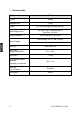
1 Technical data KERN KFS-TM Display 6-digit Weighing Units g, kg Display DMS weighing cells Range calibration LCD 16.5 mm digits with back lighting 80-100 Ω. Max. 4 item per 350 Ω; Sensitivity 2-3 mV/V We recommend ≥ 50 % max. Input voltage 220 V – 240 V, 50 Hz Electric Supply Mains adapter secondary voltage 12V, 500 mA Housing Admissible ambient temperature Net weight Rechargeable battery (optional) 260 x 150 x 65 0°C – 40°C 1.5 kg 40 h / 12 h Operating / charge time Table leg incl.
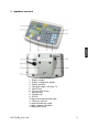
2 Appliance overview 1. Display “weight” 2. Display “average item weight“ 3. Display “quantity” 4. Tolerance margin, see chap. 7.8 5. ON/OFF key 6. Tare and zero set key 7. Numeric keys 8. Function keys 9. RS-232 10. Input connection load cell cable 11. Table leg / wall unit 12. End stop table leg / tripod 13. Mains adapter connection 14.
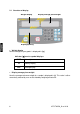
2.1 Overview of display Weight display Display average piece weight Display quantity • Weight display Here the weight of your goods is displayed in [kg]. Indicator [] next to symbol displays: TARE • Net weight Stability display a Zeroing display Display average piece weight Here the average reference weight of a sample is displayed in [g]. This value is either numerically entered by user or calculated by weighing on balance.
• Display quantity Here the current piece quantity (PCS = pieces) or in totalizing mode the sum of the placed parts is displayed, see chapter 7.7.
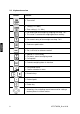
2.2 Keyboard overview Button Function Turn on/off Taring (> 2 % Max) Zero setting (< 2 % Max) For entering of item weight by weighing see chap. 7.6.1 This value is saved to the weighing balance memory For numeric entry of item weight see chap. 7.6.2 Reference optimisation Set / call limits for tolerance control Addition in sum memory Exit menu, return to weighing mode Call up total Calculate weighing data via interface Call function menu Confirm selection in menu ….
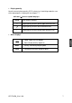
2.3 Audio signal 1 x briefly Confirm by pressing key 1 x longer Saving was successful 2 x briefly Invalid entry 3 x briefly Missing entry continuous Tolerance control depending on menu setting ”F1 Co“, see chap. 8 3 Basic Information (General) 3.1 Utilisation in accordance with specification. The display unit acquired by you is used in combination with a weighing plate and serves to determine the weighing value of material to be weighed.
3.3 Warranty Warranty claims shall be voided in case • Our conditions in the operation manual are ignored • The appliance is used outside the described uses • The appliance is modified or opened • Mechanical damage or damage by media, liquids, natural wear and tear • The appliance is improperly set up or incorrectly electrically connected • The measuring system is overloaded 3.
5 Transport and storage 5.1 Testing upon acceptance When receiving the appliance, please check packaging immediately, and the appliance itself when unpacking for possible visible damage. 5.2 Packaging / return transport Keep all parts of the original packaging for a possibly required return. Only use original packaging for returning. Prior to dispatch disconnect all cables and remove loose/mobile parts. Reattach possibly supplied transport securing devices.
Major display deviations (incorrect weighing results) may be experienced should electromagnetic fields (e.g. due to mobile phones or radio equipment), static electricity accumulations or instable power supply occur. Change location or remove source of interference. 6.2 Scope of delivery / standard accessories: • For display unit, see chapter 2 • Mains adapter • • Table leg incl. wall fixture Protective cover • Operating manual 6.
(Example of illustration) To position the display higher up, the display unit may be mounted on an optionally available tripod (KERN IFB-A01/A02).
6.4 Mains connection Power is supplied via the external mains adapter. The stated voltage value must be the same as the local voltage. Only use original KERN mains adapters. Using other makes requires consent by KERN. 6.
Call up menu: Switch-on balance and during the selftest press . Ensure that there are no objects on the weighing pan. Reset to zero if necessary by pressing . Go to weighing mode and press and hold for approx. 5-6 seconds until FUNC followed by F0 iSn appears. Release button. Press repeatedly until F2 dm is displayed. On verified weighing systems press the adjustment switch! Press and select the set weighing scales type by .
Acknowledge by and select desired setting with . = Linearization = Adjustment How to carry out adjustment: Confirm menu setting nonLin with . Ensure that there are no objects on the weighing pan. LoAd will be displayed after standstill control has been carried out. Put the required adjustment weight carefully in the centre of the weighing pan. After successful adjustment, the weighing scales will carry out a selftest.
6.6 Linearization Linearity shows the greatest deviation of a weight display on the scale to the value of the respective test weight according to plus and minus over the entire weighing range. If linearity deviation is discovered during a monitoring of test resources, you can improve this by means of linearization. • • • • • Carrying out linearization is restricted to specialist staff possessing well acquainted with the workings of weighing scales.
Call menu item linearization Confirm menu setting , see chap. 6.6 with . Ensure that there are no objects on the weighing plate. “LoAd 1” will be displayed after standstill control has been carried out. Put the first adjustment weight approx. 1/4 Max (see table 1) carefully in the centre of the weighing pan. “LoAd 2” will be displayed after standstill control has been carried out. Put the second adjustment weight approx. 2/4 max (see table 1) carefully in the centre of the weighing pan.
6.7 Verification General introduction: According to EU directive 2009/23/EC balances must be officially verified if they are used as follows (legally controlled area): a) For commercial transactions if the price of goods is determined by weighing. b) For the production of medicines in pharmacies as well as for analyses in the medical and pharmaceutical laboratory. c) For official purpose. d) For manufacturing final packages. In cases of doubt, please contact your local trade in standard.
Notes on verified weighing systems In verified weighing systems the access to menu items F1, F2, F3 of the configuration menu will be blocked. To cancel the access block, go to menu item F3 APP of the configuration menu (See chap. 12.4) and change the setting to „on”. Position of seals and adjusting switch: 1. 2. 3. 4.
7 Operation 7.1 Start-up Press , the appliance will carry out a self-test. As soon as the weight display appears, the instrument will be ready to weigh. 7.2 Switching Off Press , the display will disappear. 7.3 Zeroing Resetting to zero corrects the influence of light soiling on the weighing plate. Resetting range ± 2 % max. To unload the weighing system Press , the zero display as well as the indicator [] next to a will appear. 7.4 Simple weighing Place goods to be weighed on balance.
7.5 Weighing with tare Deposit weighing vessel. After successful standstill control press the button. Zero display and the indicator [] next to T AR E appear. The weight of the container is now internally saved. Weigh the material, the net weight will be indicated. After removing the weighing container, the weight of the weighing container appears as negative display.
7.6.1 Determination of the average piece weight by weighing Set reference Reset balance to zero or tare the empty weighing container if necessary. Place on the weighing plate a known number (e.g. 10 items) of individual pieces as a reference. Wait for the stability display, than enter the number of individual items via the numeric keypad. Acknowledge with . The balance determines the average piece weight.
7.6.2 Numeric input of the average piece weight Set reference Enter established item weight by pressing numeric keys and confirm by pressing . Count the items Tare if necessary, place weighing good and read off the number of items. Delete reference Press 24 , the average unit weight will be deleted.
7.7 Totalization Adding-up during weight display: Weight display: Currently placed weight Item weight display: Selected item weight Item quantity display: Currently placed quantity of items Currently placed weight Selected item weight Currently placed quantity of items Adding-up during item display: Press , the display changes to item display.
7.7.1 Manual totalizing With this function the individual weighing values are added into the summation memory by pressing and edited, when an optional printer is connected. Menu settings: „F12 AC“ „5 AC 1“, see chap. 8 „F8 UA“ „4 UA 5“ see chap. 8 Calculate the average item weight (see chap. 7.6.1) or enter it manually (see chap. 7.6.2). Place weighing goods A. Currently placed weight Selected item weight Currently placed quantity of items Wait for stability display, then press .
Place goods to be weighed B. Wait for stability display, then press . The displayed value (e.g. 20 pieces) will be added to the summation memory and printed if an optional printer is connected. ------------------------------------------G N: C PCS: UW 2.000kg 2.000kg 0.000kg 20pcs 20.000g ------------------------------------------ The total weight, the number of weighings as well as the total number of pieces will shortly appear (Indicator [] next to TOTAL).
Display and output sum „Total“: Unload the weighing pan and press , the total weight, the number of weighings, followed by the total number of pieces will be shown for 2 sec and printed if an optional printer is connected. Indicator: T otal weight Number weighing proces s es Total number of pieces Printout example: ------------------------------------------C PCS: 7.
Delete weighing data: Press to display the total weight, the number of weighing procedures and the total quantity for 2 sec. During this display press KFS-TM-BA_IA-e-1410 .
7.7.2 Automatic adding-up With this function the individual weighing values are automatically added into the summation memory when the balance is unloaded and edited, when an optional printer is connected. Menu settings: „F12 AC“ „5 AC 0“, see chap. 8 „F8 UA“ „4 UA 5“ see chap. 8 Add up: Calculate the average item weight (see chap. 7.6.1) or enter it manually (see chap. 7.6.2). Place weighing goods A.
Add more weighed goods as described before. Please note that the weighing system must be unloaded between the individual weighing procedures. This process may be repeated 99 times or till such time as the capacity of the weighing system has been exhausted. Display and output sum „Total“: Unload the weighing pan and press , the total weight, the number of weighings, followed by the total number of pieces will be shown for 2 sec and printed if an optional printer is connected.
7.8 Tolerance check The weighing scales allow weighing goods according to a target quantity or target weight within specified tolerances. With this function one can also check if the weighing good is within a defined tolerance range. Reaching target quantity is indicated by an audio sound (if enabled in menu) and a visual signal (Tolerance margin ) displayed. For menu settings, see chapter 8: Target quantity / target weight with tolerances 2 limits For menu setting, „F3 Pn ” see chap.
Activate function For menu setting „F0 sel“, see chap.
Display limits 1. Tolerance check for target weight Press to display the lower limit for target weight including current setting. Press to display the upper limit for target weight including current setting. 2. Tolerance check for target quantity Press Press to display the lower limit for target quantity including current setting. to display the upper limit for target quantity including current setting.
7.8.1 Tolerance check for target quantity Activate menu setting „F0 sel / SEL 2“, see chap.7.8 „Activate function“. Set limit values Press to display the lower limit including current setting. If required, delete the current setting by pressing . Use the numeric keys to enter the quantity for the lower limit (such as 70 units) and confirm by pressing . The upper limit will be displayed with the current setting. Delete with if necessary.
Start tolerance check Specify unit weight, see chap. 7.6.1 or 7.6.2 Place load and wait until tolerance margin [] appears. With the help of the tolerance indicator check if the weighed goods are under, inside or over the default tolerance. Depending on the setting in the menu an additional audio signal may be sounded.
7.8.2 Tolerance check for target weight Menu setting „F0 sel / SEL 1“, „Enable function“. Set limit values Press to display the lower limit including current setting. Delete with if necessary. Use the numeric keys to enter the weight for the lower limit value (such as 3 kg) and confirm by pressing . The upper limit for the target weight including current setting will be displayed. Delete with if necessary.
Use the numeric keys to enter the upper limit (such as 4 kg) and confirm by 38 KFS-TM-BA_IA-e-1410 .
Start tolerance check Place load and wait until tolerance margin [] appears. With the help of the tolerance indicator check if the weighed goods are under, inside or over the default tolerance. Depending on the setting in the menu an additional audio signal may be sounded.
8 Function menu Navigation in the menu: Call up menu In weighing mode keep pressed until F S E t appears. Release button. The first menu item F0. SEL is displayed. long pressing: Select menu items With help of , the individual menu items can be selected one after the other.
Change settings Confirm selected menu item with setting will be shown. and the current Change setting in selected menu item by pressing Confirm setting Return to weighing mode KFS-TM-BA_IA-e-1410 Confirm required setting with to the menu. Press to return to weighing mode . and the appliance returns .
Overview: Menu item Available settings F0 SEL 1 SEL0 Tolerance control disabled Enable tolerance check 1 SEL1 1 SEL2* Tolerance control for weighing F1 Co 11 Co0 Display conditions of the tolerance marker 11 Co 1* F2 Li 12 Li 0 Tolerance range F3 Pn Number of limiting points F4 bU Audio signal F5 Ao Automatic zero point correction (zero tracking) F6 At Automatic cutout F7 AP 12 Li 1* 13 Pn 0 13 Pn 1* 14 bu0* 14 bu1 14 bu2 2 Ao0 2 Ao1 2 Ao2* 2 Ao3 2 Ao4 on off 3 Ap0* Automatic shutdown f
F9 bl. 41 bl 0 1200 bps Baud rate 41 bl1 2400 bps 41 bl 2 4800 bps 41 bl 3 9600 bps F10 PA 42 Pr0* No parity bit Parity 42 Pr1 Odd parity 42 Pr2 Even parity Sd0 on* Autom. printout enabled on zero display Sd0 of Autom. printout disabled on zero display 5 AC 0 For automatic totalizing see chap. 7.7.2 With this function the individual weighing values are automatically added into the summation memory when the balance is unloaded and edited, when an optional printer is connected.
9 RS 232C interface You can print weighing data automatically via the RS 232C interface or manually by pressing via the interface according to the setting in the menu. This data exchange is asynchronous using ASCII - Code. The following conditions must be met to provide successful communication between the weighing system and the printer. • Use a suitable cable to connect the display unit to the interface of the printer. Faultless operation requires an adequate KERN interface cable.
Connection to PC: PC D‐ SUB9P 9.2 Balance D‐ SUB9P TXD 3 2 RX D RX D 2 3 TXD GND 5 5 GND DCO 1 RT S 7 CT S 8 DSR 6 DT R 4 Remote control instructions Command Function S Stable weighing value for the weight is sent via the RS232 interface W Weighing value for the weight (stable or unstable) is sent via the RS232 interface T No data are sent, the balance carries out the tare function. Z No data are sent, the zero-display appears.
10 Servicing, maintenance, disposal 10.1 Cleaning Before cleaning, disconnect the appliance from the operating voltage. Please do not use aggressive cleaning agents (solvents or similar agents), but a cloth dampened with mild soap suds. Take care that the device is not penetrated by fluids and polish it with a dry soft cloth. Loose residue sample/powder can be removed carefully with a brush or manual vacuum cleaner. Spilled weighing goods must be removed immediately. 10.
11 Error messages, troubleshooting guide In case of an error in the program process, briefly turn off the appliance and disconnect from power supply. The weighing process must then be restarted from the beginning. Fault Possible cause The displayed weight does not glow. • • • The display unit is not switched on. Mains power supply interrupted (mains cable defective). Power supply interrupted. (Rechargeable) batteries are inserted incorrectly or empty No (rechargeable) batteries inserted.
12 Installing display unit / weighing bridge Installation / configuration of the weighing system must be carried out by a well acquainted specialist with the workings of weighing balances. 12.1 Technical data Supply voltage: 5 V/150mA Sensitivity 2-3 mV/V Resistance parameter 80 - 100 Ω, max 4 items per 350 Ω load cell 12.2 Weighing system design The display unit is suitable for connection to any analogue platform in compliance with the required specifications.
12.3 Connecting a platform Disconnect the display unit from the power supply. Weld the individual wires of the load cell cable to the printed circuit board. Please see diagram below for plug allocation.
12.4 Configuring display devices Navigation in the menu: Call up menu Switch-on balance and during the selftest press . To call the firm menu item , press and hold for approx. 5-6 seconds until Func followed by F0 iSn appears. Release button. Select menu items With help of , the individual menu items can be selected one after the other.
Change settings Confirm selected menu item such as F2 dm by pressing and the current setting will be displayed. Change setting in selected menu item by pressing . Confirm setting Confirm required setting with returns to the menu. and the appliance Reject setting Press Return to weighing mode KFS-TM-BA_IA-e-1410 , the unit will return to the menu Back to weighing mode press several times.
Configuration menu overview: Menu block Main menu Menu item sub menu Available settings / explanation F0 iSn - Display internal resolution F 1 Grv - Not documented F2 dm Single-range balance Confirm by pressing be selected by dESC inC , then the following menu items can . Position decimal point available selection 0, 0.0, 0.00, 0.000, 0.0000, 0.
Dual range balance Confirm with selected by dESC inC , then the following menu items can be . Position decimal point available selection 0, 0.0, 0.00, 0.000, 0.0000, 0.00000 div 1 inC 1 inC 2 inC 5 Readability for 1. Weighing range Selectable 1, 2, 5, 10, 20, 50 inC 10 inC 20 inC 50 div 2 inC 1 inC 2 inC 5 Readability for 2.
Multi-interval balance Confirm by available. , after that the following menu items are Position decimal point available selection 0, 0.0, 0.00, 0.000, 0.0000 inC div 1 inC 1 inC 2� inC 5� Readability for 1. Weighing range Selectable 1, 2, 5, 10, 20, 50 inC 10� inC 20� inC 50� div 2 inC 1� inC 2� inC 5� Readability for 2.